Rotary degassers and components therefor

a rotary degasser and impeller technology, applied in the direction of positive displacement liquid engine, charge manipulation, furnaces, etc., can solve the problems of difficult to remove broken or worn impeller shafts, environmental hazards, and wear of graphite threads of impeller shafts

Inactive Publication Date: 2013-09-03
MOLTEN METAL EQUIP INNOVIATIONS LLC
View PDF466 Cites 63 Cited by
  • Summary
  • Abstract
  • Description
  • Claims
  • Application Information

AI Technical Summary

Problems solved by technology

Known coupling-to-impeller shaft connections are usually threaded, and gas can seep past the threaded connections, especially after the threads have been worn after operation of the degasser, causing the graphite threads of the impeller shaft to wear.
The leaks waste gas, and if caustic gas such as chlorine is used, the gas can interact with nearby steel causing the steel to oxidize as well as releasing the caustic chlorine gas into the atmosphere creating an environmental hazard.
Another problem with conventional devices is that broken or worn impeller shafts are difficult to remove.
Stress is placed on the impeller shaft as it rotates and the shaft is weakened by the threads, so the impeller shaft tends to eventually break, and it typically breaks just below the coupling and the end still threaded into the coupling must be chiseled out, which is time consuming.
Although this design allows for relatively easy removal of the impeller shaft if the shaft breaks, the impeller shaft is not supported or aligned by a coupling and the impeller shaft tends to wobble and the graphite threads in the bore wear quickly.
As the fit loosens, the impeller shaft becomes more eccentric in its movement, i.e., it wobbles more, and eventually breaks.
This structure would not be used by one skilled in the art to couple a hollow shaft that functions as a gas-transfer conduit because gas could leak from the holes formed as part of the cross axial bore.
Further, many conventional devices do not adequately mix the gas being introduced into the molten metal.
The gas can become trapped in a pocket within the impeller or rotor, or is otherwise not properly dispersed into the molten metal.
Additionally, if rotated too fast in order to more thoroughly mix the gas and molten metal, “cavitation” can occur.
This causes oxidation at the surface of the bath and slag or other impurities may be formed.

Method used


Image

  • Rotary degassers and components therefor
  • Rotary degassers and components therefor
  • Rotary degassers and components therefor

Examples


Embodiment Construction

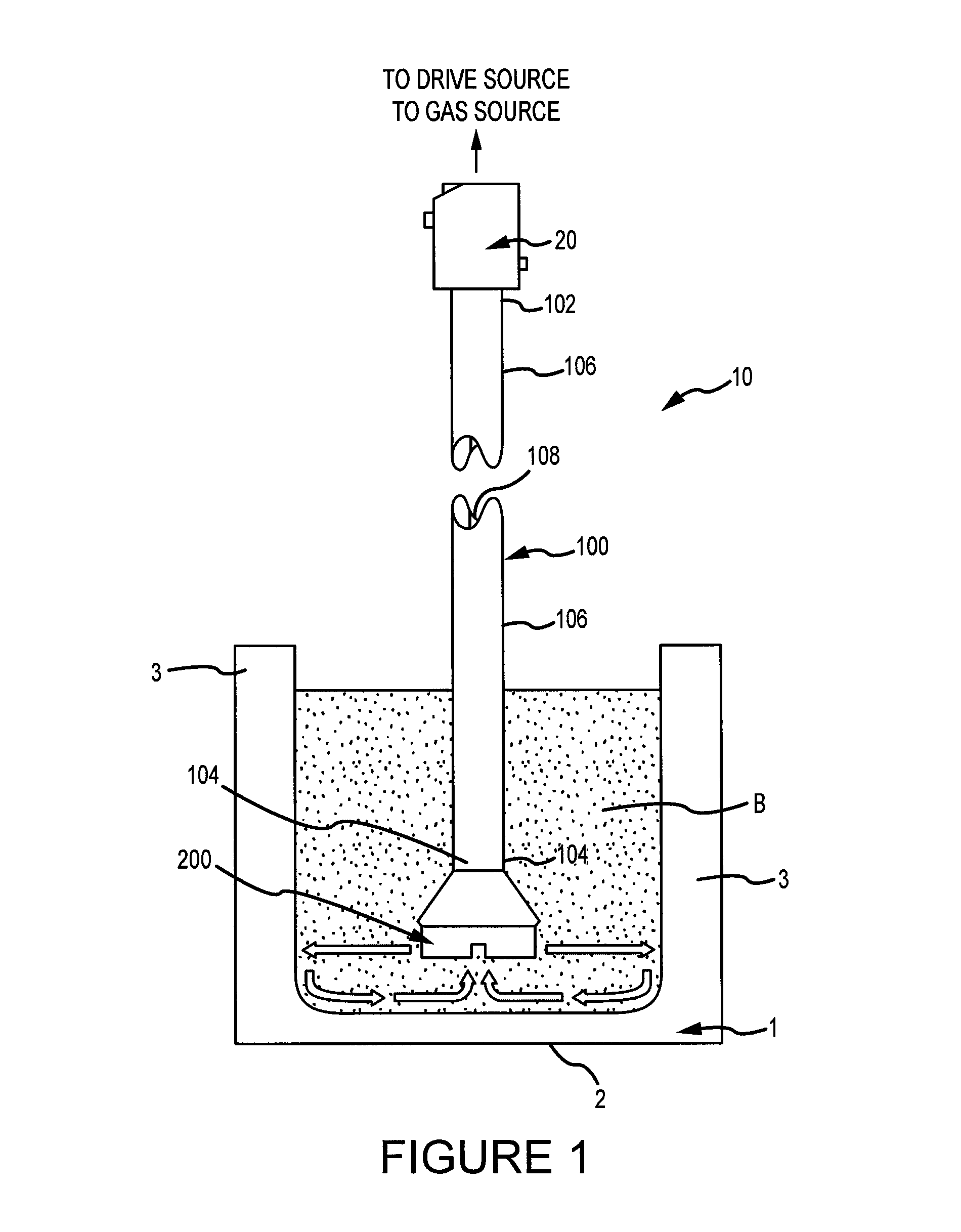
[0035]Reference will now be made in detail to the present exemplary embodiments of the invention, examples of which are illustrated in the accompanying drawings. FIG. 1 depicts a gas-release device 10 according to the invention. Device 10 is adapted to operate in a molten metal bath B contained within a vessel 1. Vessel 1 includes a bottom 2 and side walls 3. Vessel 1 may have any suitable size, shape, and configuration.

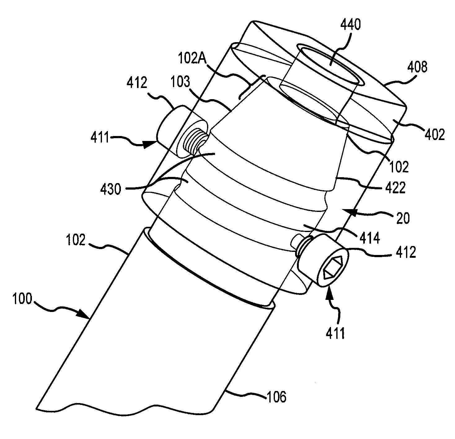
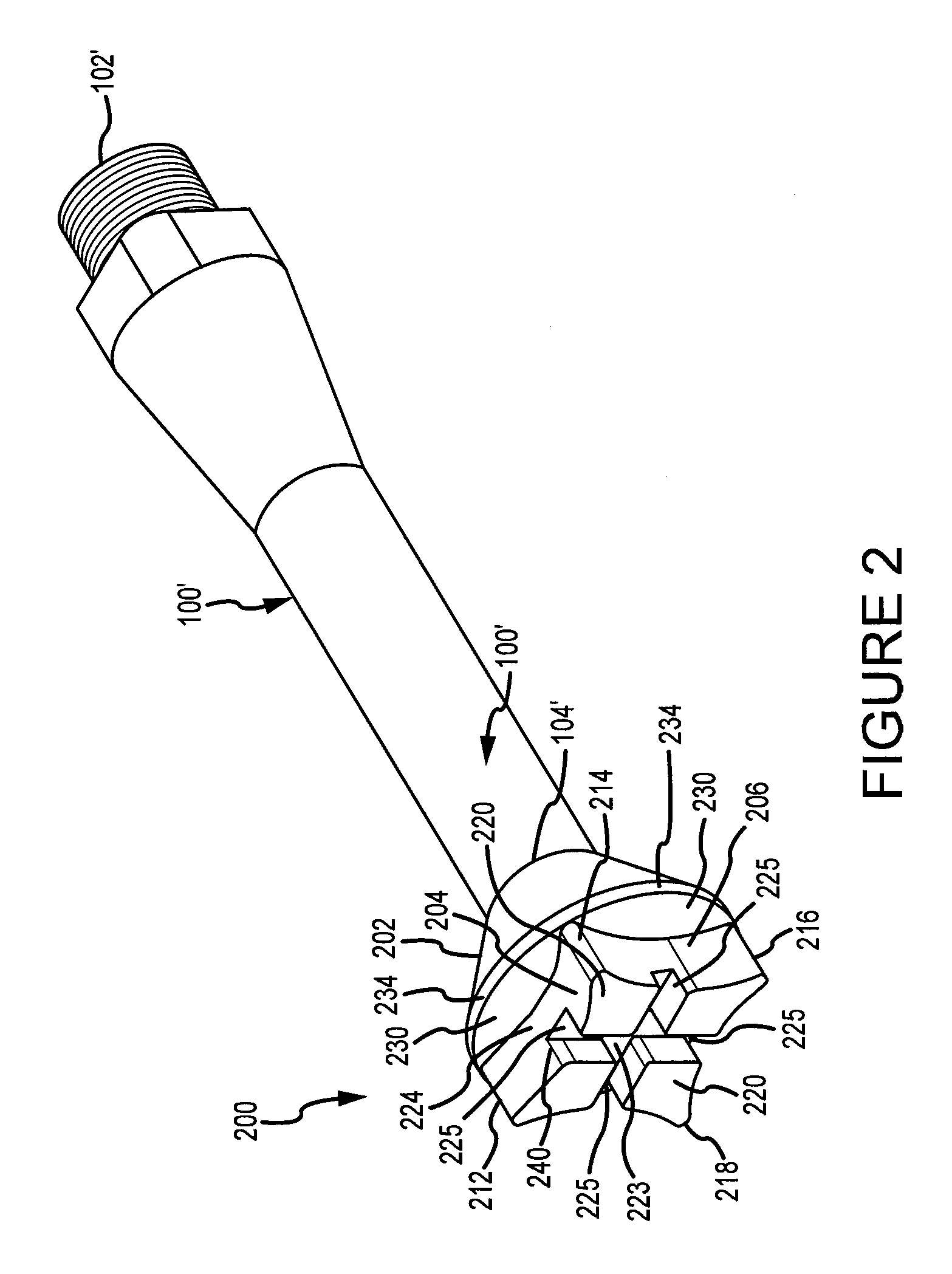
[0036]The exemplary rotary degasser 10 includes an impeller shaft 100 (also shown are shafts 100′ and 100″), an impeller 200 and a coupling 20 for coupling the impeller shaft to the motor shaft of a drive source (not shown). Impeller shaft 100, impeller 200, and each of the impellers used in the practice of the invention, are preferably made of graphite impregnated with oxidation-resistant solution, although any material capable of being used in a molten metal bath, such as ceramic, or non-impregnated graphite could be used. Oxidation and erosion treatments for graph...


PUM

PropertyMeasurementUnit
perimeteraaaaaaaaaa
areaaaaaaaaaaa
gravityaaaaaaaaaa

Abstract

Disclosed are degassers, couplings, impeller shafts and impellers for use in molten metal. One such coupling transfers gas into an impeller shaft, the coupling having a smooth, tapered internal surface to align with a corresponding surface on the impeller shaft and help prevent gas leakage and to assist in preventing damage to the impeller shaft. Improved impellers for shearing and mixing gas are also disclosed, as is a degasser including one or more of these components.

Description

PRIORITY CLAIM[0001]This application claims priority to U.S. Provisional Application No. 61 / 240,981, filed on Sep. 9, 2009, entitled “Impeller and Degasser Couplings for Molten Metal Devices,” and invented by Paul V. Cooper. The drawings and pages 29-35 of that application are incorporated herein by reference. This application is a continuation in part of and claims priority to U.S. patent application Ser. No. 12 / 853,255, entitled “Rotary Degasser and Rotor Therefor,” filed on Aug. 9, 2010 currently pending, and invented by Paul V. Cooper which claims priority to U.S. Provisional Patent Application No. 61 / 232,384 entitled “Rotary Degasser and Rotor Therefor,” filed on Aug. 7, 2009.” The disclosure of U.S. patent application Ser. No. 12 / 853,255 is incorporated herein by reference.FIELD OF THE INVENTION[0002]The invention relates to couplings, impellers and rotary degassers used in molten metal. One aspect of the invention is an impeller shaft for use with an impeller shaft that trans...

Claims


Application Information

Patent Timeline
Patent Type & Authority Patents(United States)
IPC IPC(8): F04B17/00
CPCF16C3/02F27D27/00C21C1/06F16D1/108F27D3/16F01D5/18Y10T403/25F27B3/22F27D2027/002
Inventor COOPER, PAUL V.
Owner MOLTEN METAL EQUIP INNOVIATIONS LLC
Why Eureka
Try Eureka