
Pipette and sealing tip

a technology of sealing tips and pipettes, which is applied in the direction of positive displacement liquid engines, instruments, glassware laboratories, etc., can solve the problems of leakage, other failures, and two potential failure points, and achieve the effect of reducing the need for regular pipette maintenance and calibration, high resistance, and low insertion and ejection forces

Active Publication Date: 2013-09-03
METTLER TOLEDO RAININ LLC
View PDF49 Cites 31 Cited by
  • Summary
  • Abstract
  • Description
  • Claims
  • Application Information

AI Technical Summary

Benefits of technology

[0015]Accordingly, a new seal is made every time a disposable pipette tip according to the invention is replaced. Because there is no seal between the piston and the pipette shaft, there is a reduced need for regular pipette maintenance and calibration. There is no seal to wear, break, or replace.
[0017]A pipette and tip according to the invention may benefit from low insertion and ejection forces, with a positive “snap” into place as the shaft and tip interlock as described with reference to an embodiment illustrated herein. The low insertion and ejection forces are particularly advantageous with respect to traditional, conical pipette tips and pipettes with corresponding shaft designs.
[0018]A pipette and tip as described herein may have reduced ullage space, because the piston directly penetrates and seals against the tip. This may makes the pipette easier to use, and reduce the effect of user technique on pipetting accuracy.
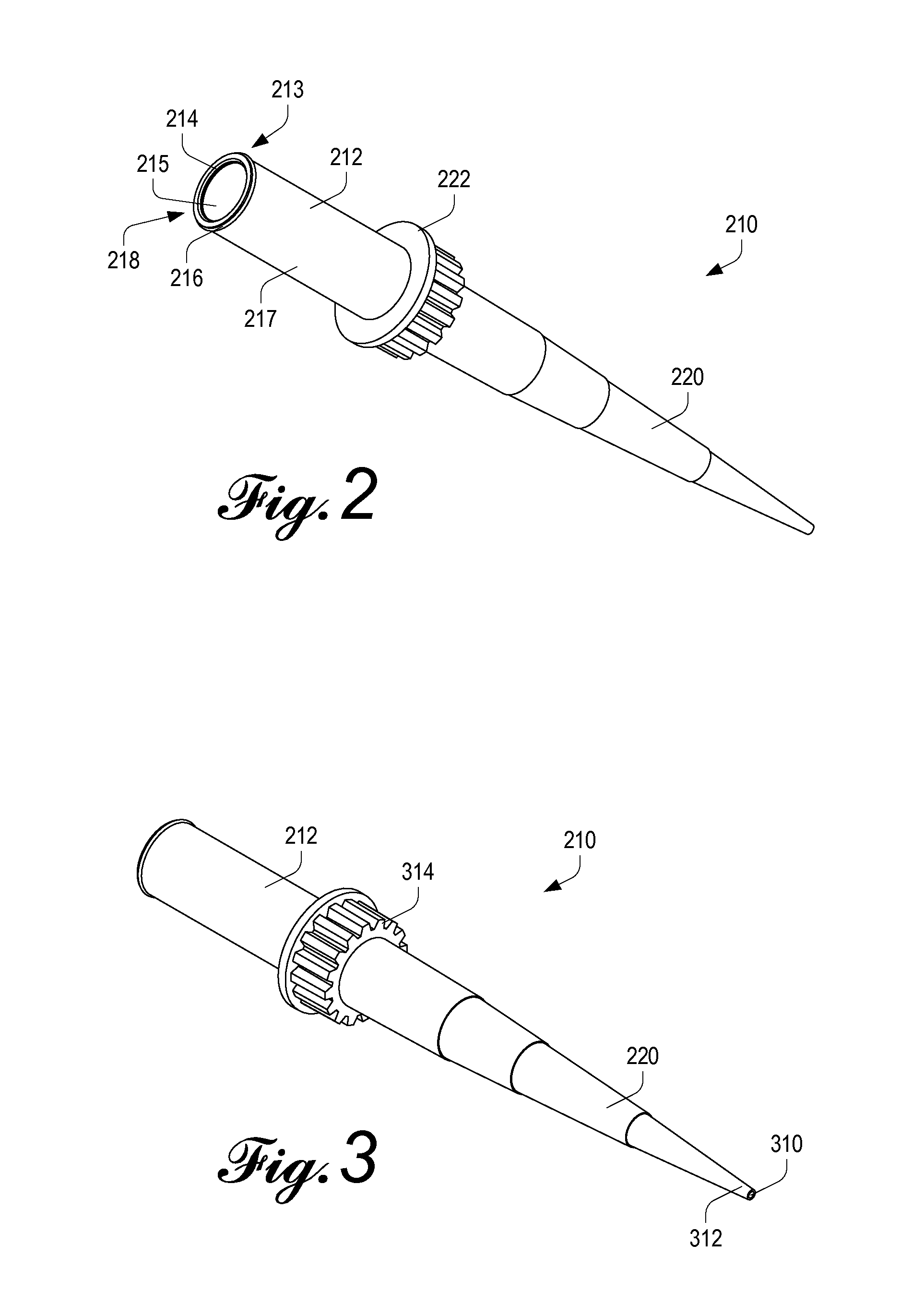
[0019]A two-piece tip configuration is described herein, which enables the optional use of an efficient low pore size membrane filter, some advantages of which are described in U.S. Pat. No. 6,045,757 to Moriarty et al. With two pieces, one for the mount end of the tip and one for the liquid handling end of the tip, two different materials may be used. Different colors may be employed. A mount material may be selected to optimize the stability of the tip on the shaft, insertion / ejection characteristics, and the mechanical interface between the tip and the shaft, since it is not necessary to maintain an air tight seal between the shaft and the tip, and the mount portion of the tip generally remains free from liquid contact. Also advantageously, the liquid handling material may be made as pure and chemical resistant as possible, without affecting mounting characteristics.
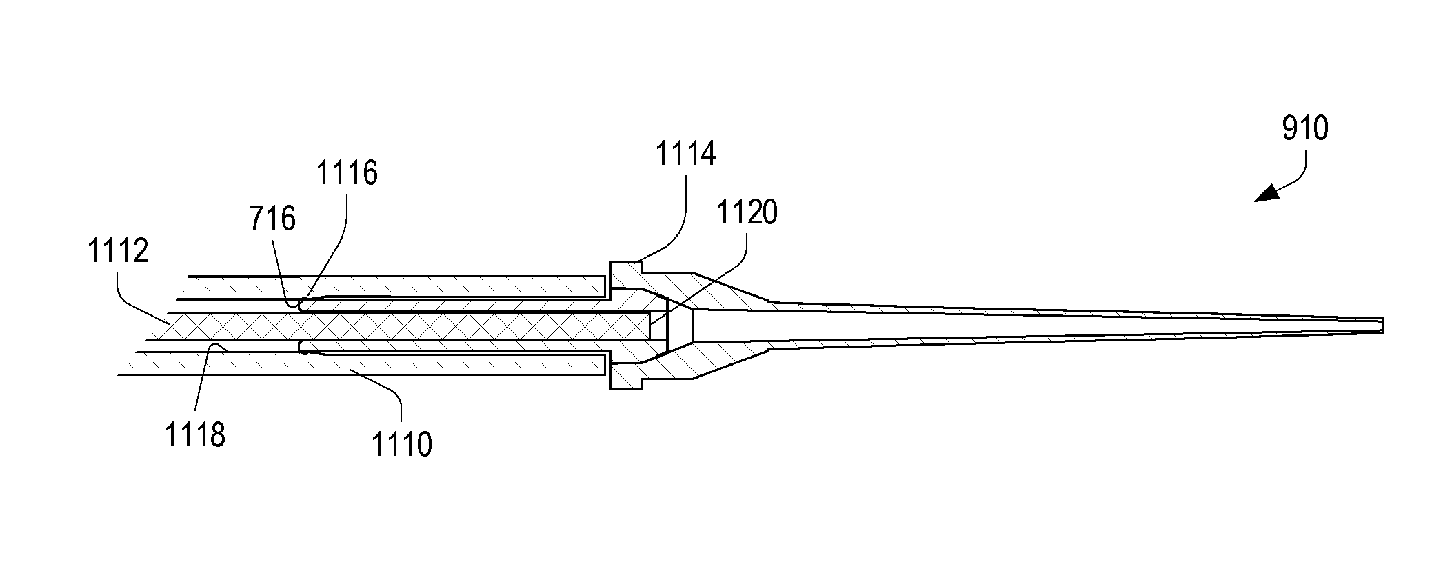
[0022]When the pipette tip is mounted on the pipette, the open proximal end of the pipette tip receives the piston, and the sealing ring forms an air tight seal around the piston. In an embodiment of the invention, a controlled amount of physical interference between an internal surface of the shaft and the proximal open end of the tip causes the open end to constrict and seal around the piston when the tip is mounted.

Problems solved by technology

Other tip mounts have been attempted but have not met with great commercial success.
There are two seals, and two potential points of failure.
This may lead to leaks and other failures, which in turn may lead to inaccuracy in liquid measurement or failure in pipetting operations.
In general, seal failure (such as wear, splitting, other damage, misalignment, dislodgment, corrosion, or contamination) is a common cause of pipetting failure.
These failures can lead to failed outcomes, and may be difficult to identify in advance, or even as pipetting is ongoing.
Wear and damage to the shaft in the tip mount region can also result in failures, and for this reason, plastic pipette shafts are also replaced from time to time.
Such maintenance often involves fairly significant teardown of the pipette, which requires dedicated labor and calibration upon reassembly.
It has the potential to take a pipette out of service for a period of time.
This additional movement is undesirable, and may lead to volume inaccuracies.
Moreover, the cushion of air is potentially subject to liquid evaporation into the air, heating, and cooling, and resulting expansion and contraction effects, which may further affect the accuracy of pipetting operations.
Filters also tend to impede airflow, and are relatively inefficient and expensive to produce and insert into pipette tips.
Because of this, filtered pipette tips are generally more expensive than their unfiltered counterparts.

Method used


Image

  • Pipette and sealing tip
  • Pipette and sealing tip
  • Pipette and sealing tip

Examples


Embodiment Construction

[0048]The invention is described below, with reference to detailed illustrative embodiments. It will be apparent that a system according to the invention may be embodied in a wide variety of forms. Consequently, the specific structural and functional details disclosed herein are representative and do not limit the scope of the invention.

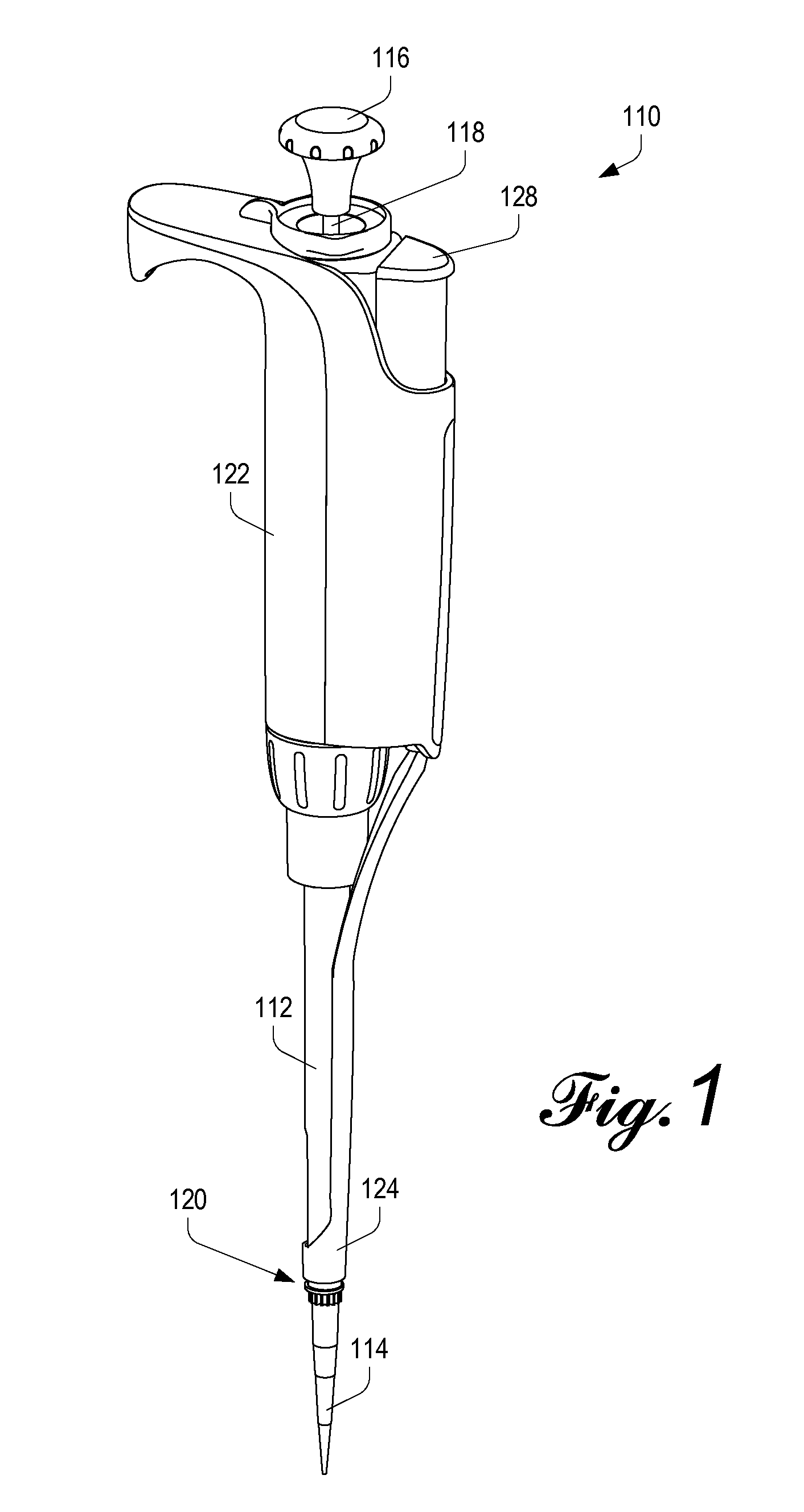
[0049]Referring initially to FIG. 1, a handheld pipette 110 according to the invention is shown. As with traditional pipettes, the illustrated pipette 110 has a tip-mounting shaft 112, and a sealing tip 114 according to the invention is shown mounted on the shaft 112.

[0050]The overall form factor of the pipette 110 and the sealing tip 114 is comparable to that of traditional pipettes, and the combination is used in the same ways and using the same techniques as would be performed using traditional pipettes.

[0051]The pipette has a plunger button 116 connected to a plunger rod 118. The button 116 and rod 118 are spring-biased to a fully-extended positi...


PUM


Abstract

A sealing pipette tip includes features to seal the tip directly against the piston in an air displacement pipette, avoiding the need for a piston seal within the pipette. This configuration reduces potential points of failure, allows the pipette-tip interface to be optimized, and improves liquid handling characteristics of the pipette.

Description

FIELD OF THE INVENTION[0001]The invention relates to air displacement pipettes and sealing disposable tips for such pipettes, and particularly to air displacement pipettes without piston seals, where piston sealing is accomplished via a structure integral to the sealing disposable tip.BACKGROUND OF THE INVENTION[0002]Handheld pipettes are commonly used to dispense or transfer small but accurately measured quantities of liquids.[0003]Air displacement pipettes are the most common variety of handheld pipettes. In an air displacement pipette, a controllable piston is mounted for movement axially within a chamber in the pipette; the piston moves in response to either manual or motorized electronic control. Typically, the piston moves in a chamber in the liquid end, or shaft, of the pipette, to which disposable pipette tips may be mounted.[0004]An air tight seal is formed between the piston and the shaft. With such a seal in place, axial movement of the piston will vary the size of the ai...

Claims


Application Information

Patent Timeline
Patent Type & Authority Patents(United States)
IPC IPC(8): B01L3/02
CPCB01L3/022B01L3/0275B01L3/021G01N2035/103G01N35/1016B01L2200/0689G01N2035/1053B01L3/02B01L2300/0681B01L2300/0832B01L2300/12B01L2300/165
Inventor PETREK, JAMES S.
Owner METTLER TOLEDO RAININ LLC
Learn More