Circular accelerator and operating method therefor

a technology of circular accelerator and operating method, which is applied in the direction of instruments, mass spectrometers, beam deviation/focusing by electric/magnetic means, etc., can solve the problems of difficult to secure reliability and difficult high-speed modulation of resonant frequency at 1 khz level, and achieve the effect of easy variation of acceleration energy

Active Publication Date: 2013-09-03
MITSUBISHI ELECTRIC CORP
View PDF13 Cites 25 Cited by
  • Summary
  • Abstract
  • Description
  • Claims
  • Application Information

AI Technical Summary

Benefits of technology

[0019]The present invention has been made to resolve the foregoing problems, and aims at providing a reliable circular accelerator that can easily vary acceleration energy using one accelerator, and does not need to vary the resonant frequency of the radio-frequency acceleration electrode portion during acceleration.
[0021]According to the present invention, a circular accelerator can be provided in which not only acceleration energy can be varied by one accelerator, but also the resonant frequency of the radio-frequency acceleration electrode portion does not need to be varied during acceleration.

Problems solved by technology

High-speed modulation of the resonant frequency at a 1 kHz level is extremely difficult in the device described in Patent Document 1.
Moreover, in the synchrocyclotron in Patent Document 1, high-speed modulation of the resonant frequency of the radio-frequency acceleration electrode portion is needed during acceleration, and since the portion to which high power is supplied is driven at as high speed as 1 kHz, it is difficult to secure reliability.

Method used


Image

  • Circular accelerator and operating method therefor
  • Circular accelerator and operating method therefor
  • Circular accelerator and operating method therefor

Examples


embodiment 1

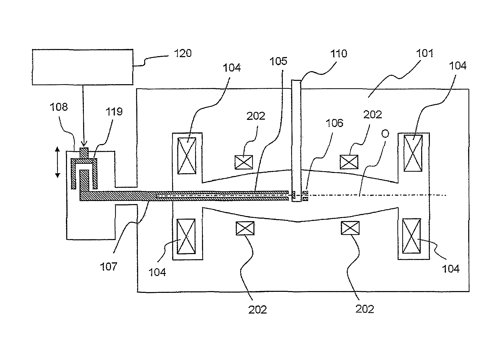
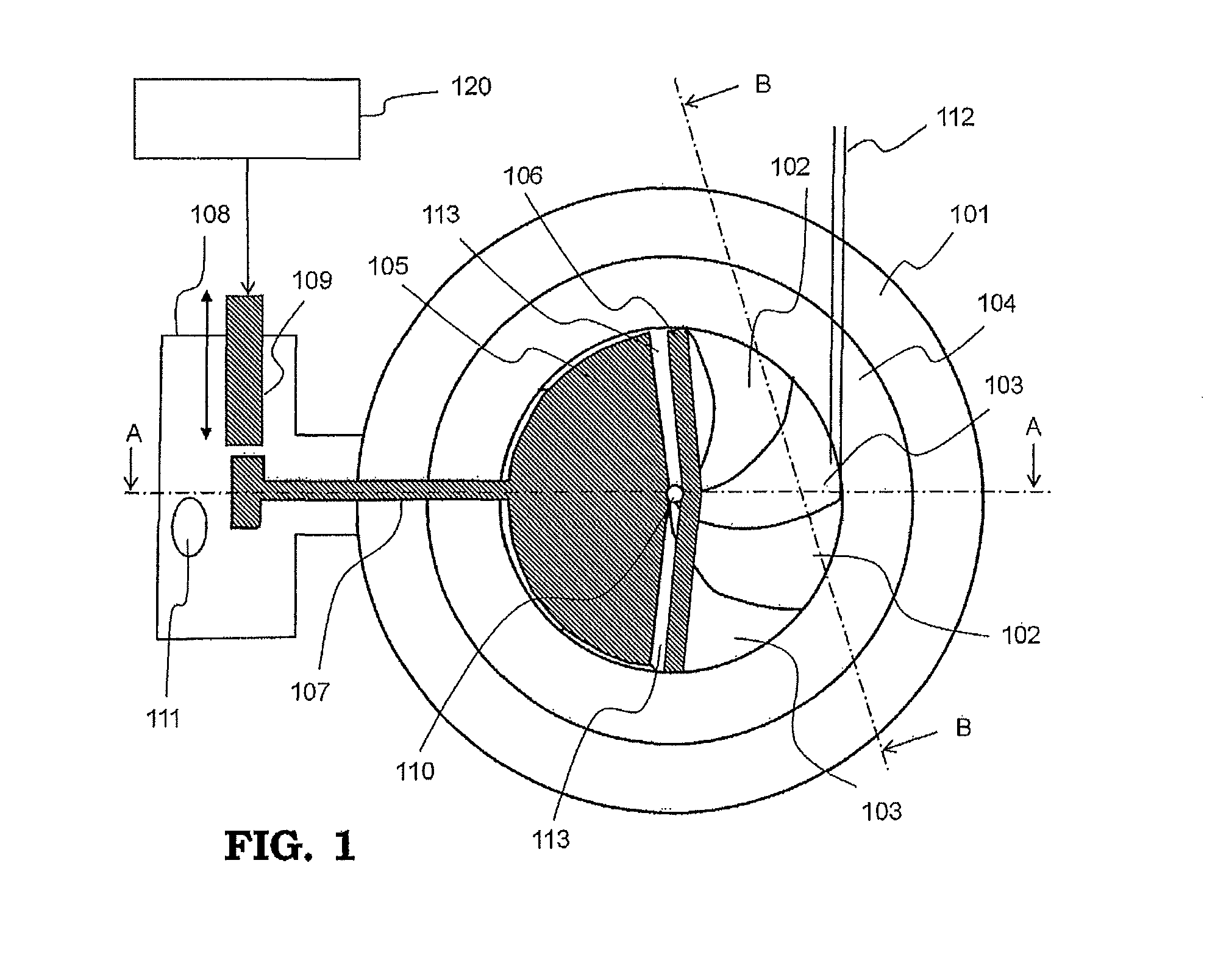
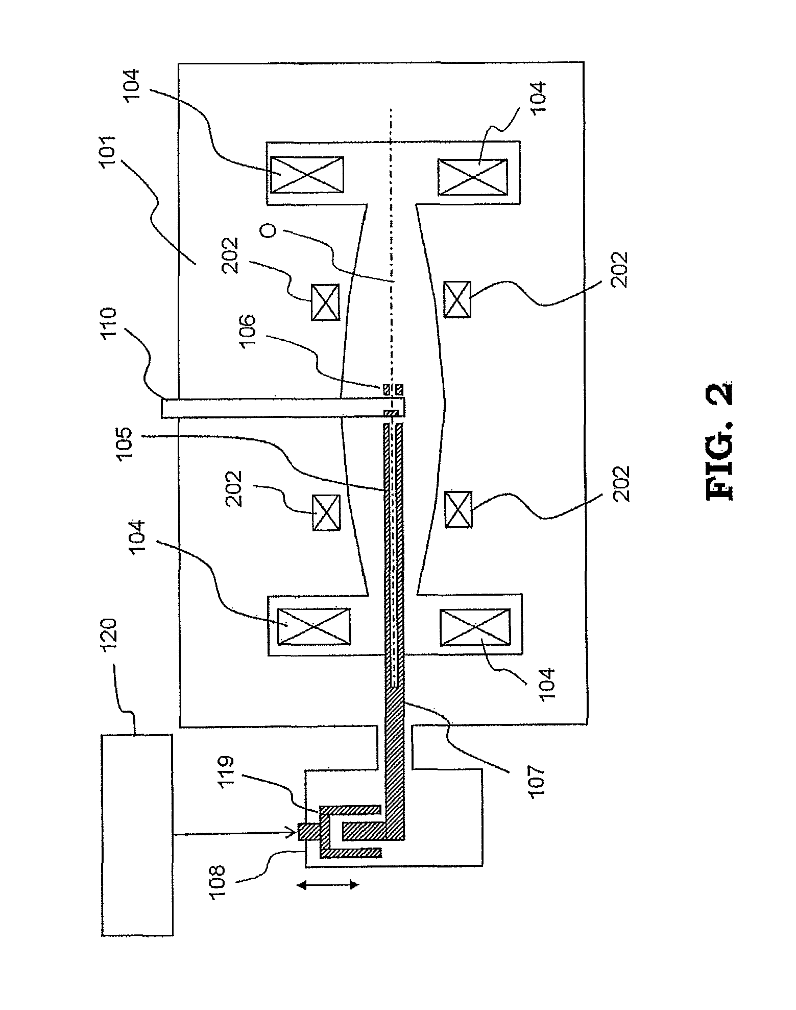
[0041]FIG. 1 is a schematic cross-sectional view showing a general configuration of a circular accelerator according to Embodiment 1 of the present invention. FIG. 1 shows device arrangement in a cross-section cut along an orbital plane in which charged particles orbit. Moreover, FIG. 2 is a schematic side cross-sectional view along the line A-A in FIG. 1. Furthermore, FIG. 3 is a side cross-sectional view along the line B-B in FIG. 1, which shows only the upper half of the configuration of an electromagnet. The configuration and operation of the circular accelerator according to Embodiment 1 of the invention will be described referring to FIG. 1 to FIG. 3.

[0042]A bending electromagnet includes an electromagnet return yoke 101, electromagnet valleys 102 each forming a wide magnetic pole gap, electromagnet hills 103 each forming a narrow magnetic pole gap, and an exciting coil 104, by which a bending magnetic field is formed in a direction perpendicular to this sheet including FIG. 1...

embodiment 2

[0064]FIG. 13 is a schematic side cross-sectional view showing a general configuration of a circular accelerator according to Embodiment 2 of the present invention, which corresponds to FIG. 2 of Embodiment 1. In FIG. 13, the same reference numerals as those in FIG. 1 and FIG. 2 show the same or corresponding parts. In this Embodiment 2, a plurality of coils for modifying a magnetic field 220 is disposed along the magnetic pole plane as shown in FIG. 13, and the coils are excited so as to generate a stronger magnetic field toward the outer side. An example of more specific disposal of the coils for modifying a magnetic field 220 is shown in FIG. 14. FIG. 14 is a view in which the magnetic pole plane of the electromagnet return yoke 101, that is, the portion where the electromagnet hills 103 and electromagnet valleys 102 are alternately repeated, is viewed from the orbital plane. The coils for modifying a magnetic field 220 are disposed on the magnetic pole faces of the electromagnet...

embodiment 3

[0068]FIG. 17 is a schematic cross-sectional view showing a general configuration of a circular accelerator according to Embodiment 3 of the present invention, which corresponds to FIG. 1 of Embodiment 1. In FIG. 17, the same reference numerals as those in FIG. 1 and FIG. 2 show the same or corresponding parts. The circular accelerator according to this Embodiment 3 differs from that in FIG. 1 in the configuration of the tuner of the radio-frequency electromagnetic field coupling part 108; the tuner of this Embodiment is made up of a rotatable condenser 129. The electrode of the rotatable condenser 129 is rotated, and thereby its capacitance is changed, so that the resonant frequency of the acceleration electrode portion is changed. In the circular accelerator of the present invention, the resonant frequency of the acceleration electrode portion is changed when energy is changed, and not changed during acceleration of charged particles. Therefore, the rotatable condenser 129 may be ...


PUM


Abstract

The circular accelerator comprises: a bending electromagnet that generates a bending magnetic field; a radio-frequency power source that generates a radio-frequency electric field in accordance with an orbital frequency of charged particles; a radio-frequency electromagnetic field coupling part connected to the radio-frequency power source; an acceleration electrode connected to the radio-frequency electromagnetic field coupling part; and an acceleration-electrode-opposing ground plate provided to form an acceleration gap between the plate itself and the acceleration electrode, for generating the radio-frequency electromagnetic field in an orbiting direction of the charged particles; wherein the bending electromagnet generates the bending magnetic field varying in such a way that the orbital frequency of the charged particles varies in a variation range of 0.7% to 24.7% with respect to an orbital frequency at the charged-particles' extraction portion, during a time of injection to extraction of the particles.

Description

BACKGROUND OF THE INVENTION[0001]1. Field of the Invention[0002]The present invention relates to a circular accelerator that accelerates charged particles to high energy while making them orbit along a near-circular spiral orbit, and extracts the accelerated charged particles to the outside thereof.[0003]2. Description of the Related Art[0004]A synchrocyclotron and cyclotron are known as the device that accelerates charged particles to high energy while making them orbit along a spiral orbit. In order to stably accelerate the charged particles in those synchrocyclotron and cyclotron, the following are required: A predetermined radio-frequency acceleration electric field is applied in a beam-traveling direction in accordance with the timing of the particles crossing an acceleration electrode. Predetermined converging force is provided in the beam-traveling direction and also in a direction perpendicular to the beam.[0005]In a synchrocyclotron as described in Patent Document 1, for ex...

Claims


Application Information

Patent Timeline
Patent Type & Authority Patents(United States)
IPC IPC(8): H05H13/00
CPCH05H7/12H05H13/02H05H13/005
Inventor TANAKA, HIROFUMIYAMAMOTO, KAZUOHARUNA, NOBUYUKIPU, YUEHUSHINKAWA, KANJIKASHIMA, TAKAYUKI
Owner MITSUBISHI ELECTRIC CORP
Why Eureka
Try Eureka