Cooling system and control method of cooling system

a technology of cooling system and control method, which is applied in the direction of driver input parameters, external condition input parameters, gas pressure propulsion mounting, etc., can solve the problems of unusual noise, make the driver and the other passengers feel odd and uncomfortable, etc., to reduce the potential for unusual noise, effectively prevent the driver and the other passengers from feeling odd and uncomfortable, and determine the noise level

Active Publication Date: 2013-09-03
TOYOTA JIDOSHA KK
View PDF45 Cites 11 Cited by
  • Summary
  • Abstract
  • Description
  • Claims
  • Application Information

AI Technical Summary

Benefits of technology

[0004]In the cooling system and the control method of the cooling system, there would thus be a demand for preventing the driver and the other passengers from feeling odd and uncomfortable by the occurrence of unusual noise in the course of cooling down a battery or an accumulator.
[0007]The cooling system according to this aspect of the invention has the air blow mode switchover module arranged to change over the status of each air flow path between the open position and the closed position in each of the multiple air blow modes of taking in the air from different locations and blowing the intake air to the accumulator. In response to a switchover demand of the active air blow mode during the air blow to the accumulator via the air blow mode switchover module, the cooling system of the invention performs the air blow restriction change over control. The air blow restriction changeover control sequentially controls the air blower to restrict the air blow to the accumulator, controls the air blow mode switchover module to switch over the active air blow mode after restriction of the air blow to the accumulator, and controls the air blower to release the restriction of the air blow to the accumulator after the switchover of the active air blow mode by the air blow mode switchover module. This arrangement reduces the potential unusual noise, such as wind roar, occurring in the course of a switchover of the air blow mode by the air blow mode switchover module and thus effectively prevents the driver and the other passengers from feeling odd and uncomfortable.
[0012]The control method according to this aspect of the invention controls the cooling system having the air blow mode switchover module arranged to change over the status of each air flow path between the open position and the closed position in each of the multiple air blow modes of taking in the air from different locations and blowing the intake air to the accumulator. In response to a switchover demand of the active air blow mode during the air blow to the accumulator via the air blow mode switchover module, the control method of the invention performs the air blow restriction changeover control. The air blow restriction changeover control sequentially controls the air blower to restrict the air blow to the accumulator, controls the air blow mode switchover module to switch over the active air blow mode after restriction of the air blow to the accumulator, and controls the air blower to release the restriction of the air blow to the accumulator after the switchover of the active air blow mode by the air blow mode switchover module. This arrangement reduces the potential unusual noise, such as wind roar, occurring in the course of a switchover of the air blow mode by the air blow mode switchover module and thus effectively prevents the driver and the other passengers from feeling odd and uncomfortable.
[0013]In the control method according to this aspect of the invention, the control method may perform the air blow restriction changeover control in response to a noise level in a passenger compartment of the motor vehicle of less than a preset reference level, while controlling the air blow mode switchover module to switch over the active air blow mode without restriction of the air blow to the accumulator in response to the noise level in the passenger compartment of not less than the preset reference level. This arrangement desirably prevents the driver and the other passengers from feeling odd and uncomfortable by utilizing masking effects of the noise in the passenger compartment on unusual noise, such as wind roar, occurring due to the operations of the air blow mode switchover module. In the control method according to this aspect of the invention, the control method may perform the control in a motor vehicle equipped with an internal combustion engine, and may determine the noise level in the passenger compartment based on a rotation speed of the internal combustion engine and controls the air blow mode switchover module to switch over the active air blow mode. Furthermore, in the control method according to this aspect of the invention, the control method may perform the control in a motor vehicle equipped with an audio output device configured to output sound with an adjustable volume in the passenger compartment, and determine the noise level in the passenger compartment based on a volume adjustment condition of the audio output device and controls the air blow mode switchover module to switch over the active air blow mode.

Problems solved by technology

In the cooling system of this prior art structure, the operations of a blower fan and the damper for blowing the air to the battery to cool down the battery cause unusual noise, such as wind roar.
The occurrence of unusual noise in the course of cooling down the battery thus makes the driver and the other passengers feel odd and uncomfortable.

Method used


Image

  • Cooling system and control method of cooling system
  • Cooling system and control method of cooling system
  • Cooling system and control method of cooling system

Examples


Embodiment Construction

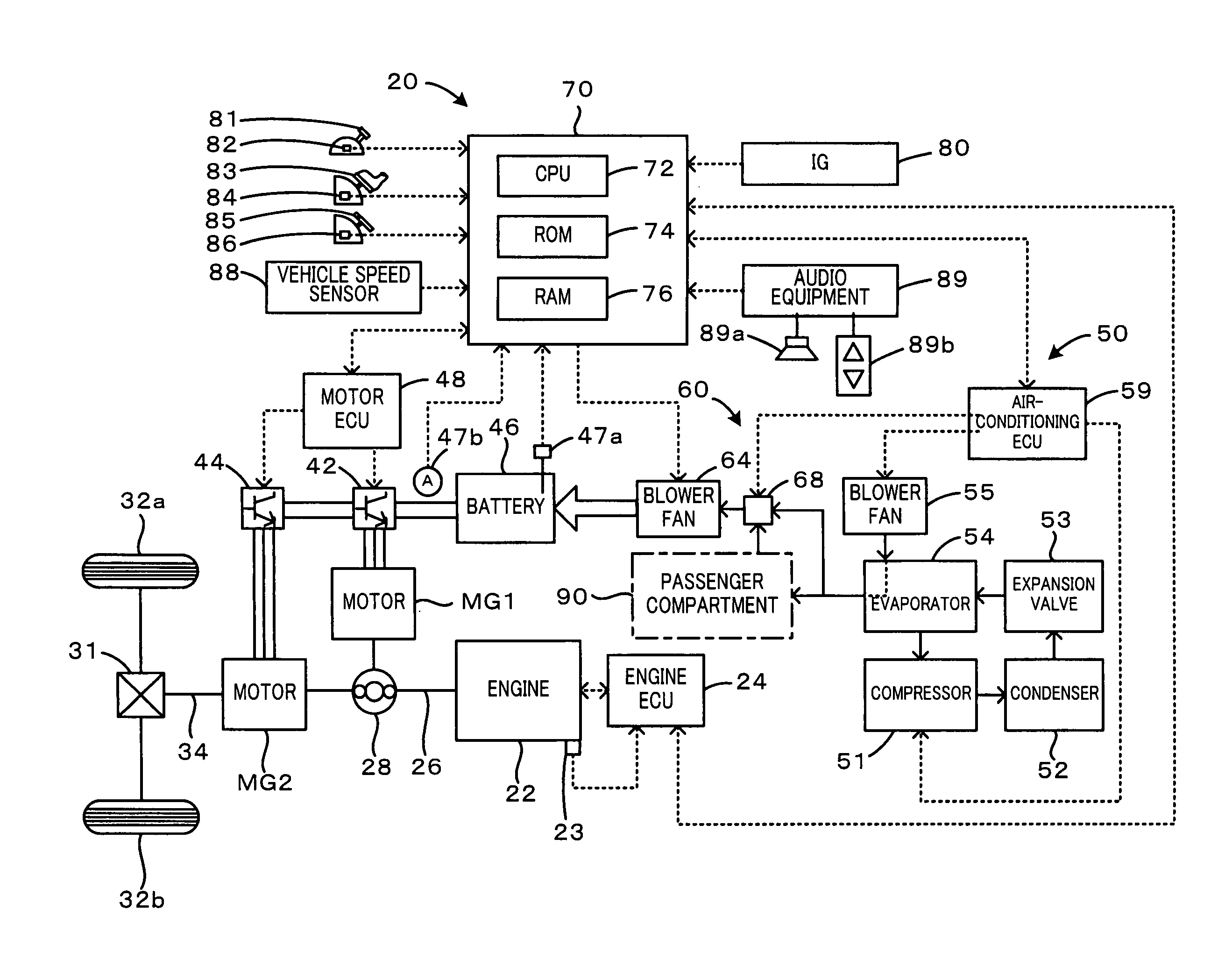
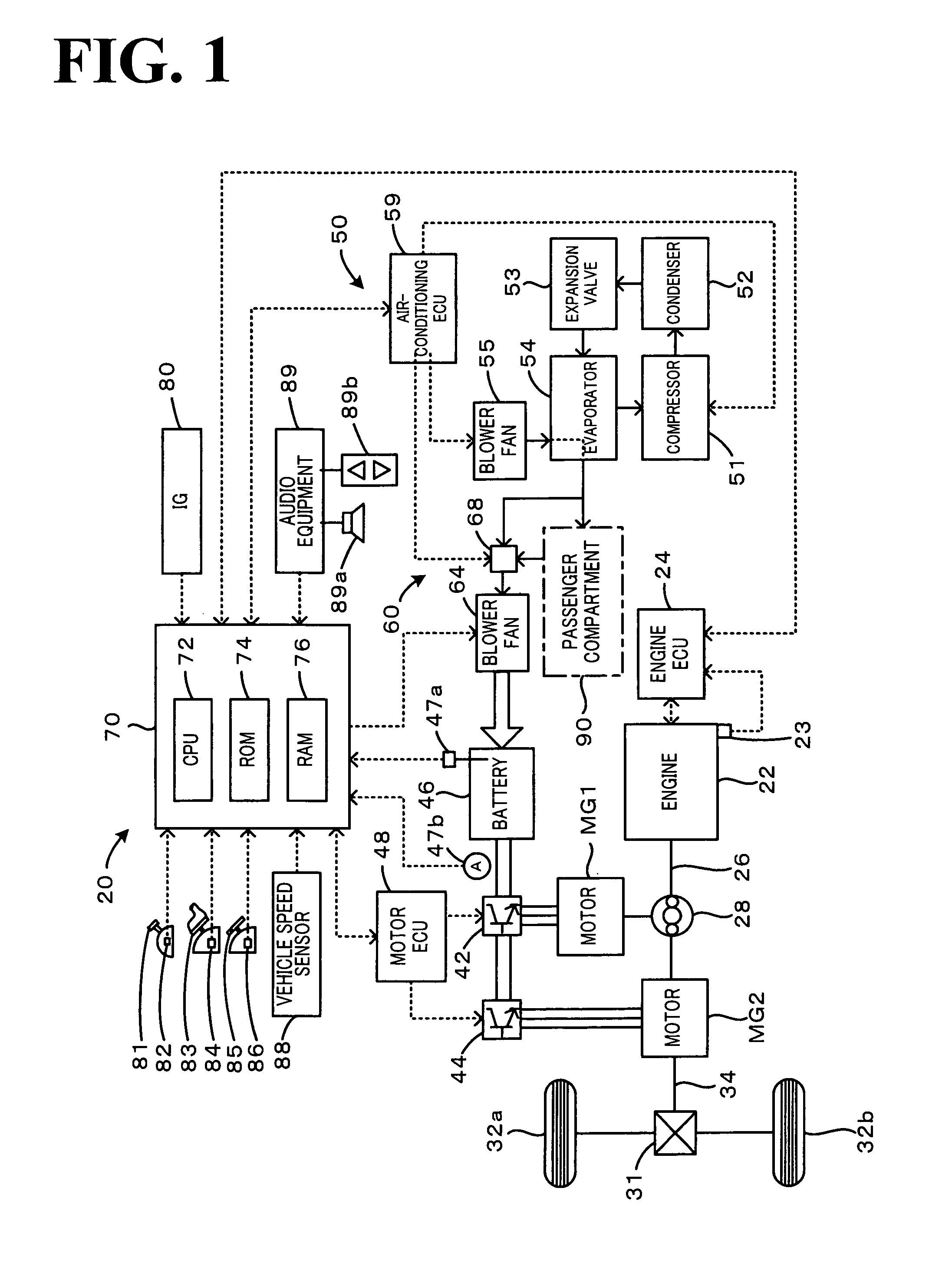
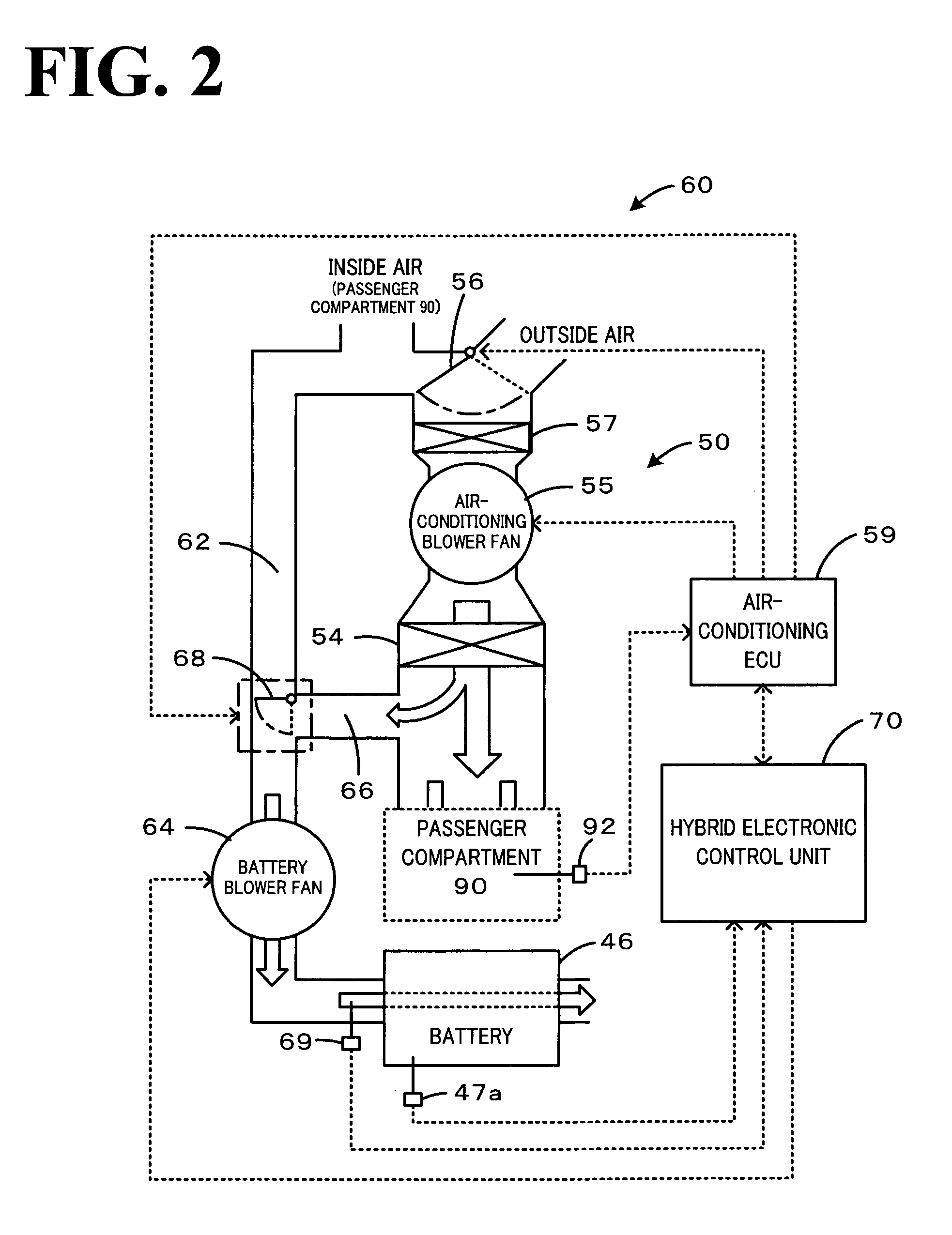
[0023]One mode of carrying out the invention is described below as a preferred embodiment with reference to the accompanied drawings. FIG. 1 schematically illustrates the configuration of a hybrid vehicle 20 in one embodiment of the invention. FIG. 2 shows the schematic structure of a cooling system 60 for a battery 46 in the embodiment. As illustrated in FIG. 1, the hybrid vehicle 20 of the embodiment has an engine 22, a planetary gear mechanism 28 having a carrier connected to a crankshaft 26 of the engine 22 and a ring gear connected to a driveshaft 34 that is linked with drive wheels 32a and 32b via a differential gear 31, a motor MG1 connected with a sun gear of the planetary gear mechanism 28 and designed to have power generation capability, a motor MG2 designed to input and output power from and to a driveshaft 34, the battery 46 arranged to transmit electric power to and from the motors MG1 and MG2 via inverters 42 and 44, an air conditioner 50 configured to condition the ai...


PUM

PropertyMeasurementUnit
temperatureaaaaaaaaaa
speedaaaaaaaaaa
rotation speedaaaaaaaaaa

Abstract

A cooling system constructed to cool down an accumulator mounted on a motor vehicle is herein presented. The cooling system sequentially controls an air blower to restrict the air blow to the accumulator, controls the air blow mode switchover module to switch over the active air blow mode after restriction of the air blow to the accumulator, and controls the air blower to release the restriction of the air blow to the accumulator after the switchover of the active air blow mode by the air blow mode switchover module.

Description

TECHNICAL FIELD[0001]The present invention relates to a cooling system configured to cool down an accumulator mounted on a motor vehicle, as well as to a control method of such a cooling system.BACKGROUND ART[0002]One proposed structure of a cooling system mounted on a motor vehicle changes over the position of a damper to change over the air blow pathway for cooling down the battery between an air flow path of taking in the air inside or outside of a passenger compartment of the motor vehicle and blowing the intake air to a battery and an air flow path of taking in the air cooled down by an evaporator and blowing the cooled intake air to the battery (see, for example, Patent Documents 1 and 2). This prior art cooling system changes over the position of the damper based on the temperature of the battery, in order to keep the battery operated in an adequate temperature range.Patent Document 1: Japanese Patent Laid-Open No. 2005-93434Patent Document 2: Japanese Patent Laid-Open No. 20...

Claims


Application Information

Patent Timeline
Patent Type & Authority Patents(United States)
IPC IPC(8): G05B15/00B60H1/00B60H1/22B60K6/445B60K11/06B60L50/16B60W10/26B60W10/30B60W20/00H01M10/60H01M10/613H01M10/625H01M10/633H01M10/6563H01M10/6566H01M10/663
CPCB60H1/00278B60K1/04B60K6/28B60K6/365B60K6/445B60L1/003B60L11/1874H01M10/5004H01M10/5016H01M10/5022H01M10/5067H01M10/5095B60H1/004Y02T10/6239B60H2001/003B60K1/02B60K2001/005B60L2240/486B60L2240/662B60W2510/244B60W2520/10B60W2540/10B60W2540/12B60W2540/16B60W2550/12Y02T10/6269Y02T10/7005Y02T10/705Y02T10/7291Y02T90/16H01M10/625H01M10/633H01M10/663H01M10/6563H01M10/613B60L58/26B60W2555/20Y02T10/62Y02T10/70Y02T10/72Y02E60/10
Inventor KIKUCHI, YOSHIAKIOMI, YASUMITSUWAKAO, SHINJITSUCHIYA, TAKENORIKATASHIMA, MIKIONAKASHIMA, KAZUHIKOISHIHARA, TETSUYA
Owner TOYOTA JIDOSHA KK
Why Eureka
Try Eureka