System and method for stray light compensation of corneal cuts

a technology of laser surgery and compensation system, applied in laser surgery, surgery, medical science, etc., can solve the problems of unwanted visual sensation, stray light being generated, and introducing hazy or cloudy sensation into the patient's perceived visual image, so as to minimize stray light

Active Publication Date: 2013-09-10
TECHNOLAS PERFECT VISION
View PDF20 Cites 0 Cited by
  • Summary
  • Abstract
  • Description
  • Claims
  • Application Information

AI Technical Summary

Benefits of technology

[0009]In accordance with the present invention, a system and method are provided for minimizing stray light that may be caused when stromal tissue in a cornea is altered by Laser Induced Optical Breakdown (LIOB). More specifically, the main object of the present invention is to compensate for potential adverse visual sensations (e.g. haziness or cloudiness in the vision of a patient) that can result when stray light is refracted from photoaltered tissue inside the cornea. When LIOB is accomplished to specifically create so-called cylindrical surfaces in the cornea, this compensation is accomplished by creating LIOB surfaces that will undergo a predictable transition after surgery. Specifically, it is intended that these surfaces become aligned on a defined refraction cone, when the stabilizing contact lens is removed.
[0011]After surgery, when the contact lens is removed from the eye, the eye will recover from the deformation caused by the contact lens. With this recovery, there will be a transition from the conical surface (i.e. a cutting conical surface), whereon LIOB was performed during surgery, to the surface of the refraction cone that is centered on the visual axis. This transition causes the induced deformation angle Ψ to become effectively zero, and causes the deformation angle φ continue to minimize the introduction of stray light into the vision of the patient.

Problems solved by technology

When incoming light is not refracted in the manner noted above, or is otherwise scattered in some way, visual distortions or hazy (cloudy) sensations can sometimes result in the image.
As implied above, if these surfaces do not account for the refraction angle “φ” (i.e. the surfaces do not eventually conform with the appropriate refraction cone) it is possible they will cause refractions that result in stray light being generated.
As indicated above, this can cause unwanted visual sensations.
Specifically, it is known that, under certain lighting conditions, this stray light will introduce a hazy or cloudy sensation into a patient's perceived visual image.
Other known procedures, however, may also result in such “cuts.” Specifically, for one, when tissue is repeatedly impacted by a sequence of multiple laser pulses, the result can be a compromise of the tissue.
Still, an unwanted consequence may be the introduction of stray light.

Method used


Image

  • System and method for stray light compensation of corneal cuts
  • System and method for stray light compensation of corneal cuts
  • System and method for stray light compensation of corneal cuts

Examples


Embodiment Construction

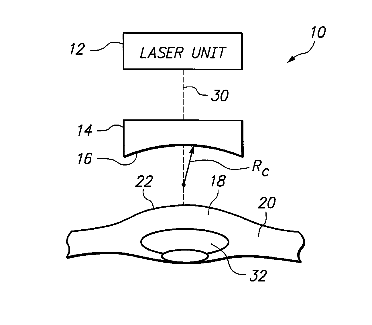
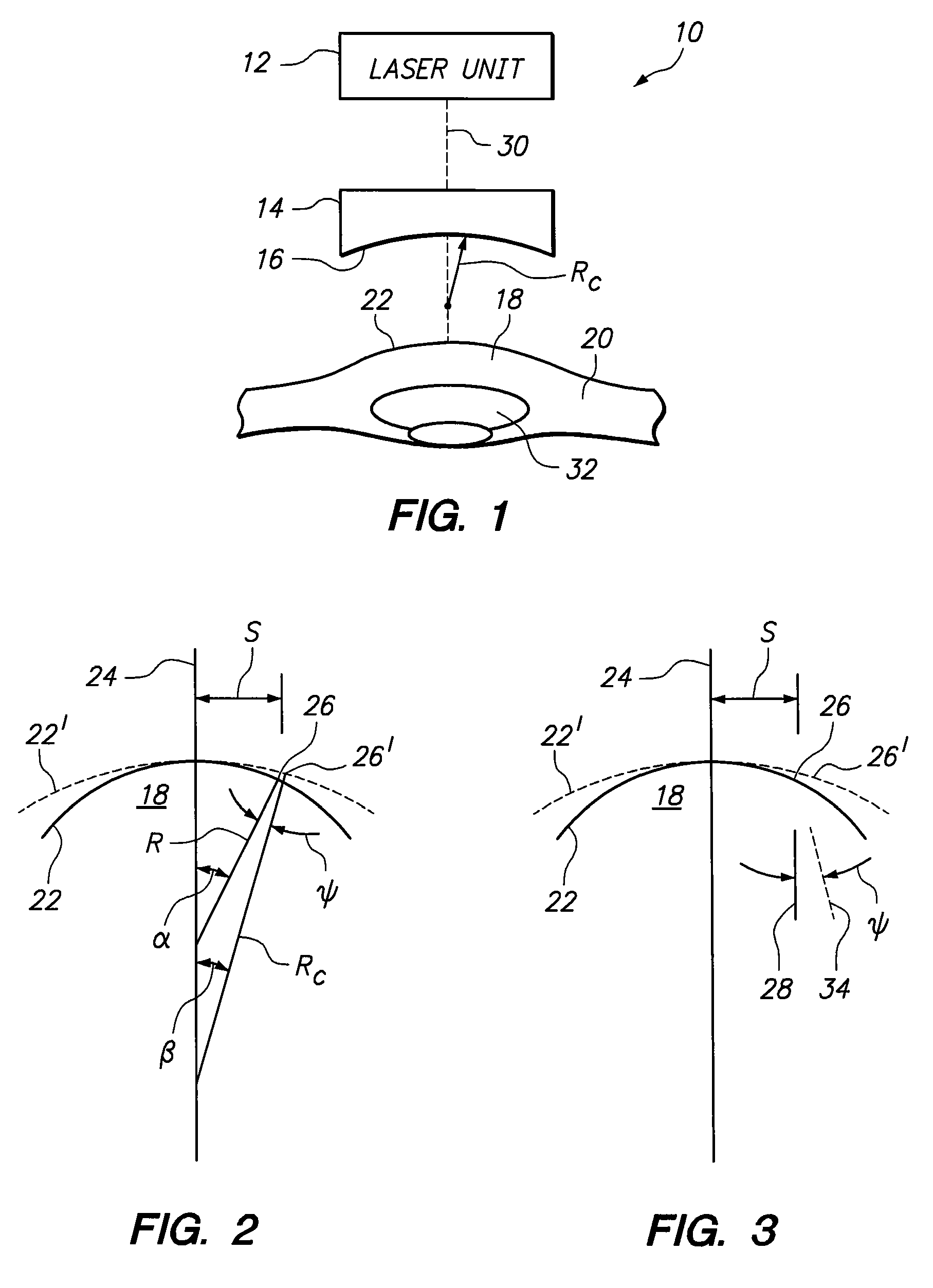
[0019]Referring initially to FIG. 1, a system for minimizing stray light caused by LIOB of stromal tissue is shown and is generally designated 10. As shown, the system 10 includes a laser unit 12 and a contact lens 14. Also, the contact lens 14 is shown to have a contact surface 16 that is defined by its radius of curvature “Rc”. FIG. 1 also shows a cornea 18 of an eye 20 positioned for laser surgery. During this surgery, the contact lens 14 is positioned against the anterior surface 22 of the cornea 18 to stabilize the eye 20.

[0020]As envisioned for the present invention, when the contact surface 16 of contact lens 14 is positioned against the anterior surface 22 of the cornea 18, the cornea 18 becomes deformed. This effectively changes the curvature of the anterior surface 22. Specifically, this involves a change from the natural, anatomical radius of curvature “R” of the anterior surface 22 of the cornea 18 to the radius of curvature “Rc” of the contact lens 14. This deformation ...


PUM


Abstract

A system and method to compensate for the deformation of an eye requires calculation of an induced deformation angle Ψ, wherein the deformation is intentionally induced during laser surgery by a contact lens, and a refraction angle φ. Specifically, during laser surgery, the cornea of an eye is typically stabilized by a contact lens. This deforms the cornea. When the contact lens is removed after the surgery, the cornea recovers from the deformation. For the present invention, the angle Ψ is calculated, and corrected by the angle φ, so that surfaces altered during surgery (e.g. by LIOB) will become substantially parallel to incoming light in the eye, after the contact lens has been removed after surgery.

Description

FIELD OF THE INVENTION[0001]The present invention pertains generally to systems and methods for performing ophthalmic laser surgery. More particularly, the present invention pertains to systems and methods for performing ophthalmic surgery that alter stromal tissue in the cornea by Laser Induced Optical Breakdown (LIOB). The present invention is particularly, but not exclusively, useful when LIOB is used to weaken corneal tissue on selected surfaces in the cornea for subsequent reshaping of the eye by intraocular pressure in the eye.BACKGROUND OF THE INVENTION[0002]Light effectively enters an eye substantially parallel to the eye's visual axis. In a normal eye, light is refracted inside the eye (i.e. at the anterior surface of the eye) so it will be incident on the retina in a manner that allows for the creation of a visual image. More specifically, it is known that the refraction of light at the anterior surface of an eye directs the incident light toward a common point on the eye'...

Claims


Application Information

Patent Timeline
Patent Type & Authority Patents(United States)
IPC IPC(8): A61B18/18A61F9/008
CPCA61F9/008A61F9/00827A61F9/00804A61F9/009A61F2009/00872
Inventor BILLE, JOSEF F.LOESEL, FRIEDER
Owner TECHNOLAS PERFECT VISION
Why Eureka
Try Eureka