Direct-light generator for sun-sky-imitating illumination devices

a technology of illumination device and direct light, which is applied in the direction of semiconductor devices for light sources, lighting and heating apparatus, planar light sources, etc., can solve the problems of minor problems in achieving the required spatial uniformity across the emitting surface, and a1 do not properly satisfy the requirements concerning visual appearance, so as to prevent possible reflection and minimize stray light

Pending Publication Date: 2022-05-26
COELUX
View PDF0 Cites 0 Cited by
  • Summary
  • Abstract
  • Description
  • Claims
  • Application Information

AI Technical Summary

Benefits of technology

[0036]Advantageously, this allows to minimize stray light by preventing possible reflections due to a non-ideality in the absorption offered by the hollow housing inner walls.

Problems solved by technology

However, the devices described in WO 2009 / 156347 A1 do not properly satisfy the requirements concerning the visual appearance of the illumination device itself when directly viewing at it.
Applicant realized that the embodiments of the direct-light source provided in WO 2014 / 075721A1 may still in some cases exhibit minor problems in achieving the required spatial uniformity across the emitting surface, e.g. due to chromatic aberration introduced by the collimated light source.

Method used


Image

  • Direct-light generator for sun-sky-imitating illumination devices
  • Direct-light generator for sun-sky-imitating illumination devices
  • Direct-light generator for sun-sky-imitating illumination devices

Examples


Embodiment Construction

[0068]The following is a detailed description of exemplary embodiments of the present disclosure. The exemplary embodiments described therein and illustrated in the drawings are intended to teach the principles of the present disclosure, enabling those of ordinary skill in the art to implement and use the present disclosure in many different environments and for many different applications. Therefore, the exemplary embodiments are not intended to be, and should not be considered as, a limiting description of the scope of patent protection. Rather, the scope of patent protection shall be defined by the appended claims.

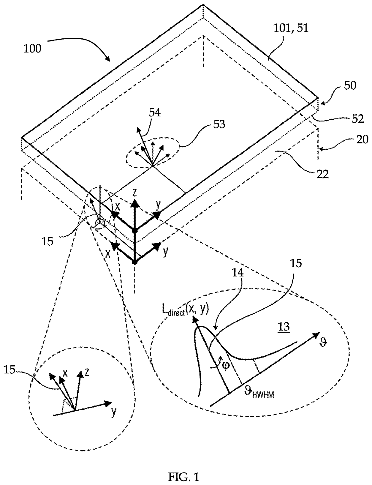
[0069]FIG. 1 schematically illustrates a sun-sky-imitating illumination device 100 which is capable of illuminating an ambient as the sun and the sky do through a window, and which guarantees at the same time a visual appearance of the illumination device that offers the experience of virtually infinite depth as the sky and the sun do in nature when they are observed th...


PUM


Abstract

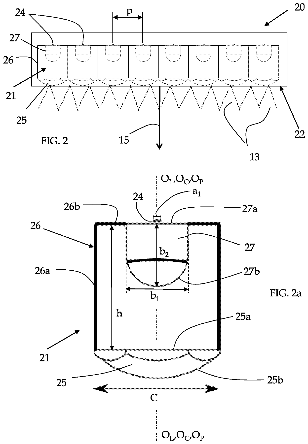
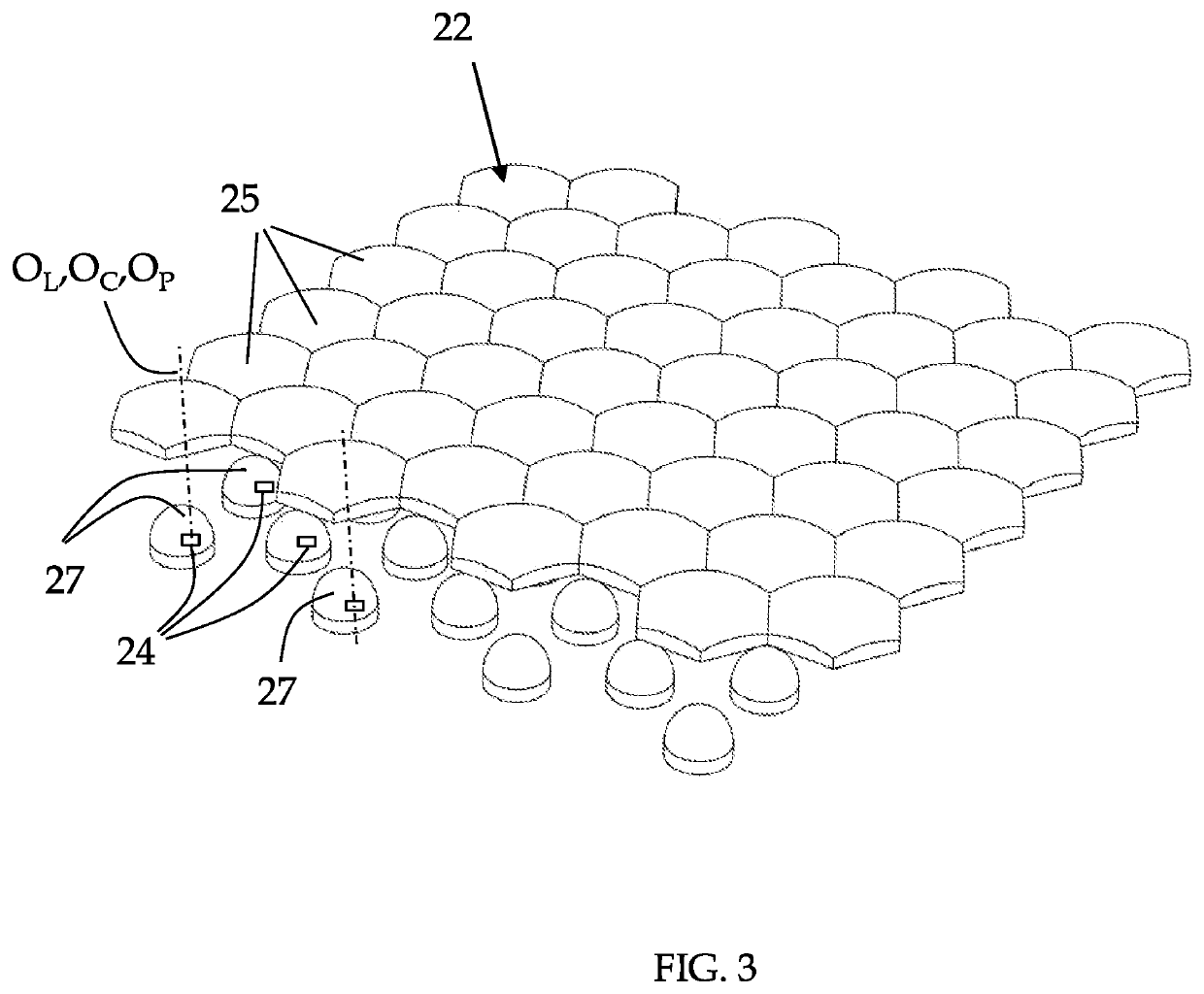
The present disclosure is directed to a direct-light generator (10) for sun-sky-imitating illumination devices (100) configured for generating natural light similar to that from the sun and the sky, comprising a first emitting surface (22) and an array of light-emitting devices (21) configured to generate from a primary light a direct light (13) which exits the first emitting surface (22) along a direct light direction (15), wherein the direct light (13) exiting the first emitting surface (22) has a luminance profile (Ldirect(x, y, θ, φ)) which has a narrow peak (14) in the angular distribution around the direct-light direction (15) and is uniform across the first emitting surface (22), wherein each light-emitting device (21) comprises a light emitter (24) having an emitting surface and at least a pair of collimation lenses (25,27) illuminated by the light emitter (24), each pair of collimation lenses (25,27) comprising a pre-collimation lens (27) comprising a light inlet surface (27a) facing the light emitter (24) emitting surface and a light outlet surface (27b), the pre-collimation lens (27) being positioned proximal to the light emitter (24) and a collimation lens (25) comprising a light input surface (25a) and a light output surface (25b), the collimation lens (25) being positioned distal from the light emitter (24), the light emitter (24) and the pre-collimation lens (27) being housed in a hollow housing (26) which is internally coated or made of light absorbing material and has at least an aperture where the collimation lens (25) is positioned, wherein the pre-collimation lens (27) of each pair of collimation lenses (25,27) is configured to emit with a substantially angularly constant intensity and to uniformly illuminate a whole light input surface (25a) of the collimation lens (25) of the pair of collimation lenses (25,27) wherein, with the pre-collimation lens having a pre-collimation lens height (b2), and a base of the input surface (25a) of the collimation lens (25) being spaced apart from a base of the inlet surface (27a) of the pre-collimation lens (27) of a lenses distance (h), the ratio (b2/h) between the pre-collimation lens height (b2) and the lenses distance (h) is comprised in the range of 0.2-0.8, more preferably in the range between 0.25-0.75 and even more preferably in the range between 0.3-0.7; and/or wherein, with the pre-collimation lens (27) having a pre-collimation lens maximum width (b1) and the collimation lens (25) having a collimation lens maximum width (C), the ratio (b1/C) between the pre-collimation lens maximum width (b1) and the collimation lens maximum width (C) is comprised in the range of 0.3-0.8, more preferably in the range between 0.35-0.75 and even more preferably in the range between 0.4-0.7.

Description

TECHNICAL FIELD[0001]The present disclosure generally relates to direct-light generators for sun-sky-imitating illumination devices which realize the perception of the natural light from the sun and the sky.[0002]More precisely, the perception of the natural light from the sky and the sun is related both to the capacity of the illumination device to illuminate an ambient with effects very similar to the effects that would manifest in the same room if an aperture with sky and sun beyond it, i.e. a window, would be positioned at the same place, and also to the appearance of the device itself when directly viewing at it, which creates the visual appearance of infinite depth for the sky and infinite position of the sun sources. Therefore, the direct-light generators for sun-sky-imitating illumination devices need to fulfill two main aims, namely[0003]to generate light with a luminance profile similar to that of the light from the sun to allow the direct light emitted by the sun-sky-imit...

Claims


Application Information

Patent Timeline
Patent Type & Authority Applications(United States)
IPC IPC(8): F21V9/02F21V3/06F21V5/00F21V9/40F21V11/06
CPCF21V9/02F21V3/0615F21Y2115/10F21V9/40F21V11/06F21V5/007F21V5/008F21Y2105/10
Inventor LOTTI, ANTONIOLI, CHENSCHREIBER, PETERHÖFER, BERND
Owner COELUX
Why Eureka
Try Eureka