Optical system for spectrometers

Active Publication Date: 2021-05-06
HITACHI HIGH TECH ANALYTICAL SCI GMBH
View PDF0 Cites 0 Cited by
  • Summary
  • Abstract
  • Description
  • Claims
  • Application Information

AI Technical Summary

Benefits of technology

[0010]It is an object of the invention to provide an optical system with only one entrance aperture and a reduced number of detectors without compromising wavelength covera

Problems solved by technology

In state of the art optical systems higher wavelength ranges typically are much more intense t

Method used


Image

  • Optical system for spectrometers
  • Optical system for spectrometers
  • Optical system for spectrometers

Examples


Embodiment Construction

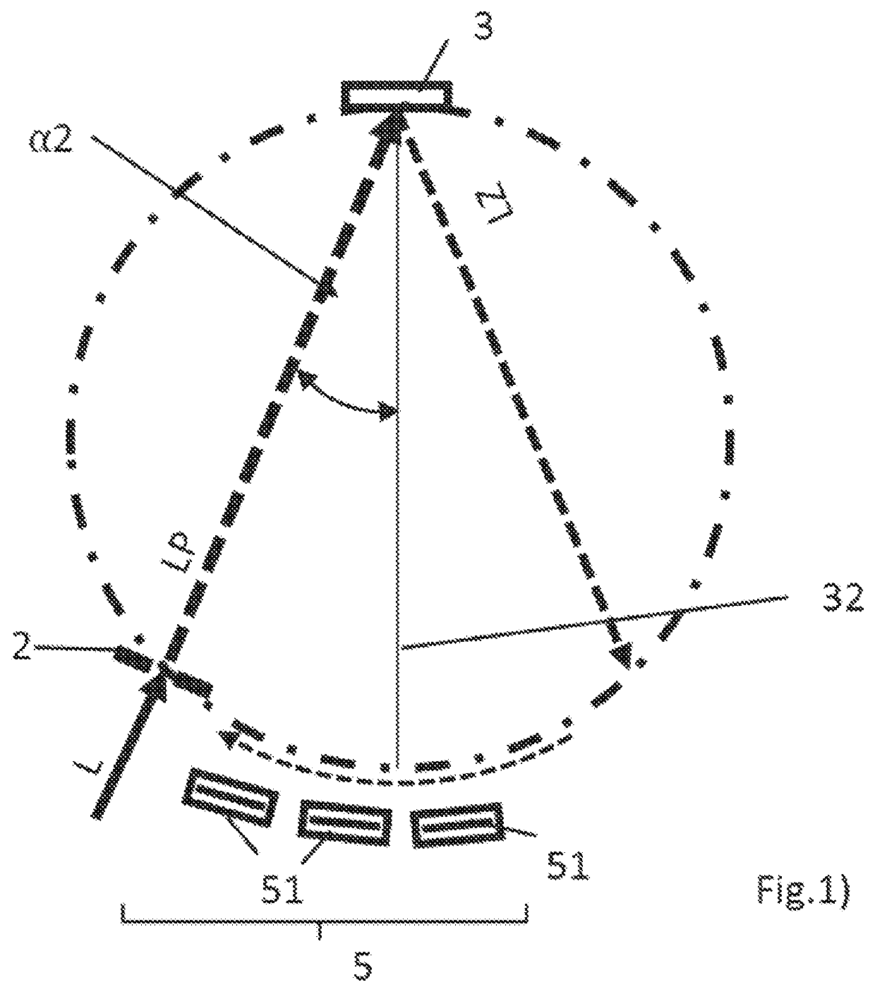
[0044]FIG. 1 shows an optical system 1 according to the prior art. In this structure the detectors 51 are arranged along the focal curve on each side of the normal 32 of the grating 3 to simultaneously measure the wavelength ranges R1, R2. In order to gain wavelength coverage and a good resolution a series of detectors are necessary.

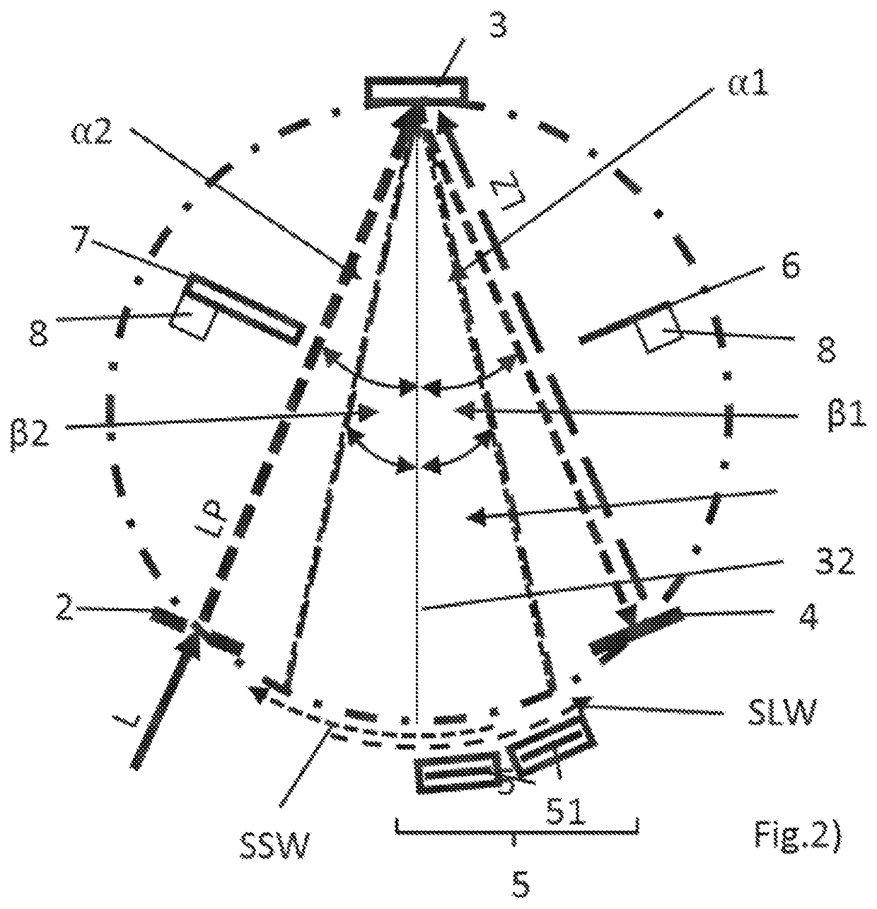
[0045]FIG. 2 shows the optical system 1 according to the invention with a decreased number of detectors 51 when it is measuring the first fan of diffracted light LD1 as well as the second fan of diffracted light LD2 simultaneously. In this mode the primary light beam LP forms a positive angle of incidence α2 and the back reflection results in a negative angle of incidence α1, each causing the respective angles of diffraction β1, β2 for wavelength λ. Thus two antidirectional spectra are formed which run in opposite directions and partly overlap each other. For the measurement, this overlap is eliminated by decomposing the wavelength ranges into their shor...


PUM


Abstract

The invention relates to an optical system, to a spectrometer device comprising such optical system and to a method to operate such an optical system comprising an entrance aperture for entering primary light containing both a first, lower wavelength range and a second, higher wavelength range into said optical system, a grating for spectral dispersion of the primary light beam into a first fan of diffracted light within the first wavelength range and a primary zero order light beam, a mirror element suitably positioned to reflect the primary zero order light beam back as secondary light beam to the grating where it is dispersed into a second fan of diffracted light within the second wavelength range, a detector arrangement with detectors, an absorber element to be reversibly placed within the primary zero order light beam, and a filter element to be reversibly placed within the primary light beam.

Description

RELATED APPLICATIONS[0001]The present invention is a Nonprovisional application under 35 USC 111(a), claiming priority to Serial No. EP 19207205.6, filed on 5 Nov. 2019, the entirety of which is incorporated herein by reference.SUBJECT OF THE INVENTION[0002]The invention relates to an optical system for spectrometers, to a spectrometer device comprising such an optical system and to a method to operate such an optical system.BACKGROUND OF THE INVENTION[0003]An optical system for spectrometers is a component used to measure properties of light over a specific portion of the electromagnetic spectrum. It is part of a spectrometer device which is used to generate spectral lines by means of arc or spark excitation, LIBS, ICP or glow discharge excitation and the like. The wavelengths and intensities of these spectral lines are measured to identify materials or analyze their chemical composition. Such spectrometer devices may operate over a wide range of wavelengths, from deep UV into far ...

Claims


Application Information

Patent Timeline
IPC IPC(8): G01J3/28G01J3/02G01J3/18
CPCG01J3/28G01J3/18G01J3/021G01J3/20G01J3/32G01J3/0232G01J3/08
Inventor RAK, MARZENA BEATASIMONS, RAINER
Owner HITACHI HIGH TECH ANALYTICAL SCI GMBH
Why Eureka
Try Eureka