Sensorless technology, estimation of sampled back EMF voltage values and/or the sampled inductance values based on the pulse width modulation periods

a sensorless, back emf voltage technology, applied in the direction of electronic commutators, synchronous motor starters, electrical apparatuses, etc., can solve the problem of limited conventional methods for high torque levels in the high and mid speed rang

Active Publication Date: 2013-09-10
MICRO BEAM SARL
View PDF4 Cites 7 Cited by
  • Summary
  • Abstract
  • Description
  • Claims
  • Application Information

AI Technical Summary

Benefits of technology

[0015]Additional objects and advantages of the various embodiments of the invention will be set forth in part in the description, or may be learned by practice of the invention. Objects and advantages of the embodiments of the invention may be realized and attained by means of the elements and combinations particularly pointed out in the claims. Embodiments of the invention are disclosed herein and set forth in the claims.

Problems solved by technology

However, these conventional methods are limited for high and mid speed ranges with high torque levels.

Method used


Image

  • Sensorless technology, estimation of sampled back EMF voltage values and/or the sampled inductance values based on the pulse width modulation periods
  • Sensorless technology, estimation of sampled back EMF voltage values and/or the sampled inductance values based on the pulse width modulation periods
  • Sensorless technology, estimation of sampled back EMF voltage values and/or the sampled inductance values based on the pulse width modulation periods

Examples


case 1

[0046]

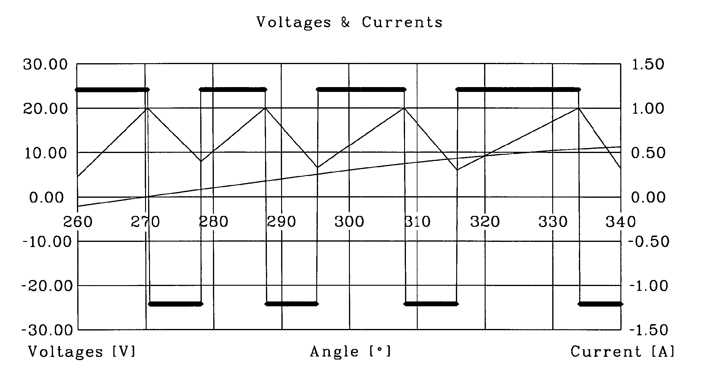
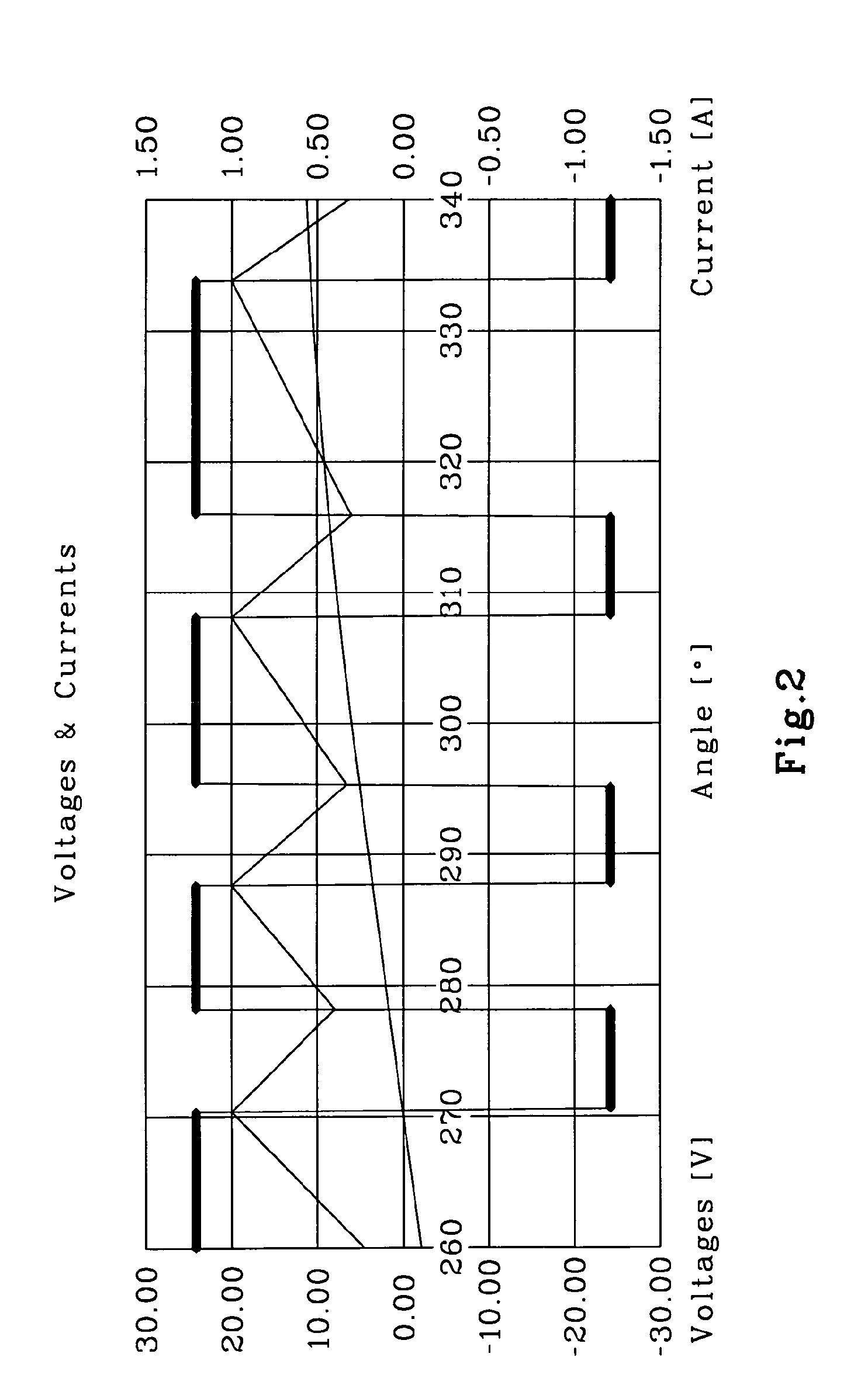
[0047]L constant, PWM double with a single compare max current limit Imax and a fixed off period Toff.

[0048]Only one equation is necessary, a complete PWM period is considered:

[0049]uapplied=Ton·24⁢V+Toff·(-24⁢⁢V)Ton+Toffi=I1⁢on+I2⁢on2=Imax-Δ⁢⁢I2di≅0dt=Ton+Toffuind=uapplied-R·i=24⁢⁢V·Ton-ToffTon+Toff-R·i

case 2

[0050]

[0051]L constant, PWM on one transistor with a single compare max current limit Imax and a fixed off period Toff.

[0052]Only one equation is necessary, a complete PWM period is considered:

[0053]uapplied=Ton·24⁢⁢V+Toff·(0⁢⁢V)Ton+Toffi=I1⁢on+I2⁢on2=Imax-Δ⁢⁢I2di≅0dt=Ton+Toffuind=uapplied-R·i=24⁢⁢V·T⁢⁢onT⁢⁢on+T⁢⁢off-R·i

[0054]Remarks: di=I1off−I2on=0 is assumed and has to be verified. This allows one to chose the consecutive periods ON and OFF that can be used (see FIG. 4, for example).

case 3

[0055]

[0056]Current limitation with 2 compare current levels: I2on=I1off=Imax, I1on=I2off=Imin, Ton and Toff are variables. The current PWM limitation can be applied on two transistors (two transistors turned off during the off period):

I1on=I2off=Imin

I2on=I1off=Imax

[0057]In this example, two equations are necessary:

[0058]Equation 1 during on period Ton:

[0059]uappliedON=Ua⁢⁢lim=24⁢⁢V⁢⁢i=I1⁢on+I2⁢on2=Imin+Imax2⁢⁢dion=Imax-Imin⁢⁢dt=Ton⁢⁢24⁢⁢V=R·Imin+Imax2+L·Imax-IminTon+uind(1)

[0060]Equation 2 during off period Toff:

[0061]uappliedOFF=-Ua⁢⁢lim=-24⁢⁢V⁢⁢i=I1⁢off+I2⁢off2⁢⁢i=Imax+Imin2⁢⁢dioff=Imin-Imax=-dion⁢⁢di=Toff⁢-24⁢⁢V=R·Imin+Imax2-L·Imax-IminToff+uind(2)

[0062]Resolution of two equations and two unknowns:

[0063]⁢2·Ua⁢⁢lim=L·Imax-IminTon+L·Imax-IminToff(1)⁢-⁢(2)⁢⁢2·Ua⁢⁢lim=1Ton+1Toff·(Imax-Imin)·L(1)⁢-⁢(2)⁢⁢2·Ua⁢⁢lim=Ton+ToffToff·Ton·(Imax-Imin)·L(1)⁢-⁢(2)⁢⁢L=2·Ua⁢⁢lim(Imax-Imin)⁢Ton·ToffToff+Ton⁢(1)⁢-⁢(2)⁢->⁢(3)⁢24⁢⁢V=⁢R·Imin+Imax2+2·Ualim(Imax-Imin)⁢Ton·ToffToff+Ton·Imax-IminTon+uind...


PUM


Abstract

The methods and devices provided herein include methods and devices for controlling a permanent magnet motor. In one implementation, a method is provided that allows for the determination of the values of the phase back EMF voltage and of the phase inductances while the phases are powered with a PWM (Pulse Width Modulation) controlled current and / or voltage.

Description

CROSS REFERENCE TO RELATED APPLICATION(S)[0001]The present application claims the benefit of priority to U.S. Provisional Patent Application No. 60 / 818,321, filed Jul. 5, 2006, entitled “Sensorless Technology, Estimation of Sampled Back EMF Voltage Values and / or the Sampled Inductance Values Based on the PWM (Pulse WidthModulation) Periods,” the disclosure of which is expressly incorporated herein by reference to its entirety.TECHNICAL FIELD[0002]The technical field of the present invention is in the area of electronics and sensorless technologies. More particularly, and without limitation, the invention relates to methods and devices for controlling a permanent magnet motor, and to methods and devices that allow for the determination of the values of the phase back EMF voltage and of the phase inductances while the phases are powered with a PWM (Pulse Width Modulation) controlled current and / or voltage.BACKGROUND INFORMATION[0003]To optimally control the powering of a synchronous m...

Claims


Application Information

Patent Timeline
Patent Type & Authority Patents(United States)
IPC IPC(8): H02P6/18
CPCH02P6/18
Inventor CARDOLETTI, LAURENTBIELER, THIERRYKOECHLI, CHRISTAINFLEURY, CHRISTIAN
Owner MICRO BEAM SARL
Why Eureka
Try Eureka