Method of forming hollow foam moldings

a hollow foam and molding technology, applied in the field of hollow foam molding, can solve the problems of insufficient lightness in weight, no methods are currently known in the art, and the molding obtained with this method,

Active Publication Date: 2013-09-17
JSP CORP
View PDF17 Cites 20 Cited by
  • Summary
  • Abstract
  • Description
  • Claims
  • Application Information

AI Technical Summary

Benefits of technology

[0012]It is, therefore, an object of the present invention to provide a blowing method for producing a light weight hollow foam molding having a thin wall with a uniform thickness.
[0013]Another object of the present invention is to provide a light weight hollow foam molding having a thin wall with a uniform thickness.

Problems solved by technology

No methods are currently known in the art to produce, by blow molding, a light weight air conditioner duct which is made of a polypropylene resin foam and which has a thin wall thickness.
The molding obtained with this method, however, has an apparent density of above 0.7 g / cm3 and is insufficient in lightness in weight, though the wall thickness thereof is thin.
When the chemical blowing agent is used in a large amount, a hollow foam molding of a polypropylene resin foam having a good appearance and an apparent density of below 0.7 g / cm3 cannot be obtained.
Further, the closed cell content of such a foam molding is disadvantageously reduced.
However, the wall thickness is so large that it is difficult to use the molding as an air conditioner duct for automobiles.
In this case, when a die lip having a small clearance is used for producing a parison with a thin wall thickness by extrusion, corrugation unavoidably occurs so that the wall thickness of the hollow molding obtained from such a parison becomes non-uniform.
With this method, therefore, it is impossible to obtain a light weight hollow foam molding having a thin wall thickness.
The technique in the above extrusion molding cannot be applied to the blow molding, because a parison cannot be drawn in the extrusion direction beyond a certain level and because the parison must be molded in a succeeding blow molding step while it is in a softened state.

Method used


Image

  • Method of forming hollow foam moldings
  • Method of forming hollow foam moldings
  • Method of forming hollow foam moldings

Examples


example 1

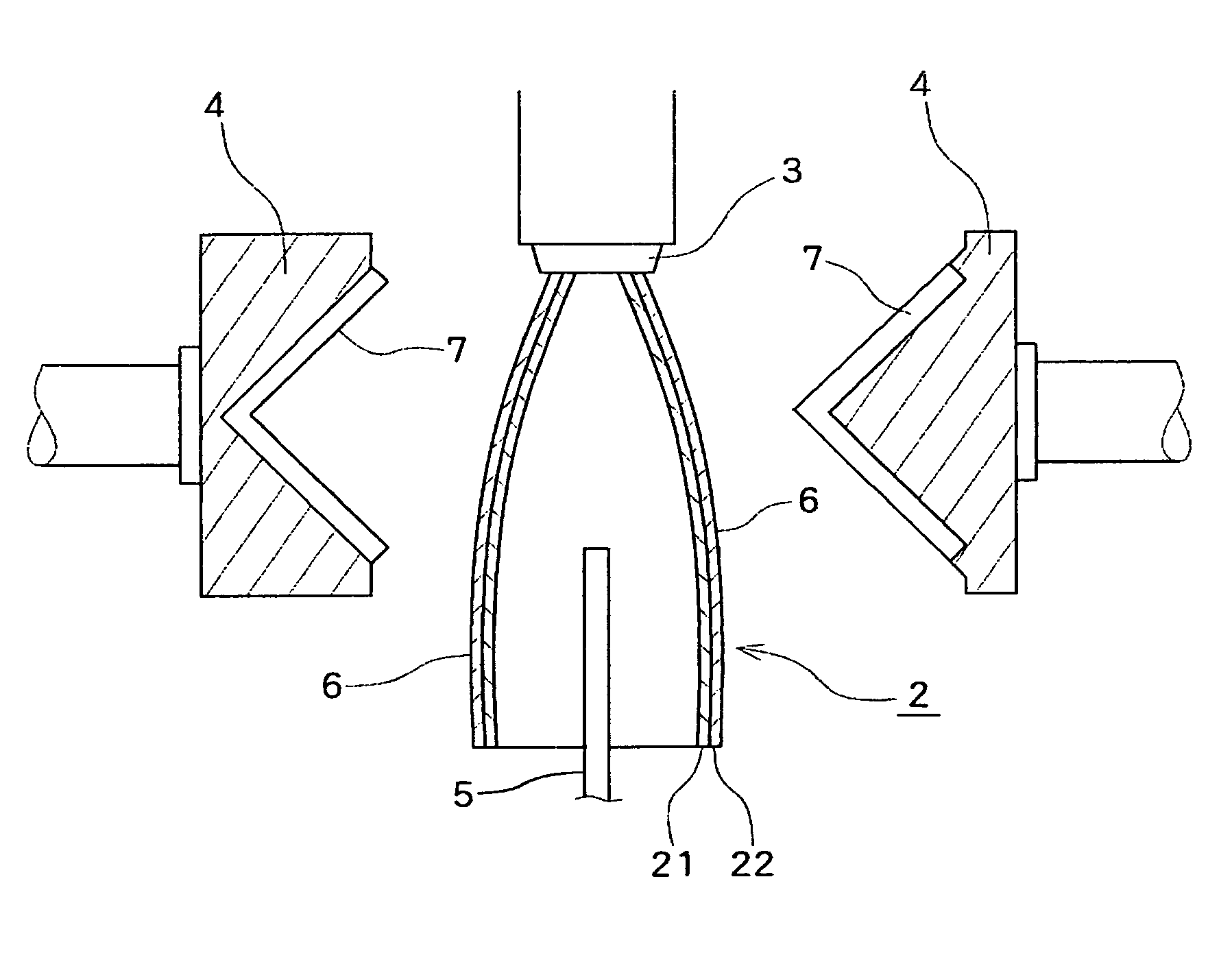
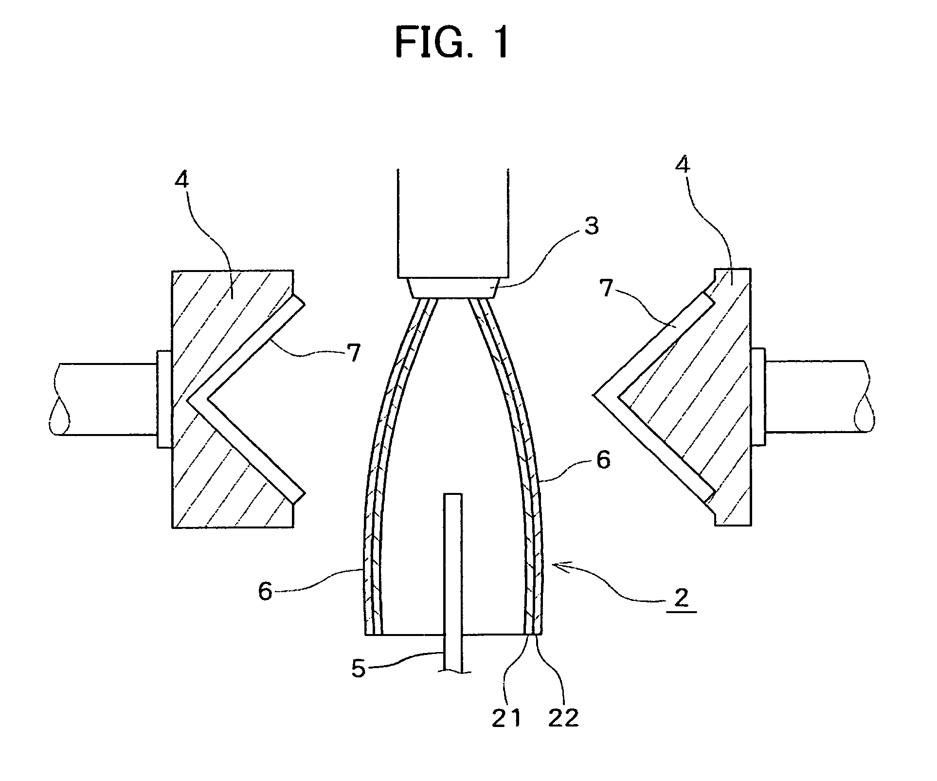
[0080]A hollow foam molding having a maximum width of 180 mm in the direction perpendicular to the extrusion direction was produced using a mixture of Polypropylene A and Polypropylene B (mixing weight ratio A / B was 20:80 as shown in Table 2) as a polypropylene resin. The equilibrium compliance Jeo and swell ratio Sw of the polypropylene resin were as shown in Table 2. A foamable melt containing the polypropylene resin, carbon dioxide gas as a blowing agent in an amount as shown Table 2 and a master batch of a cell controlling agent in an amount of 3 parts by weight per 100 parts by weight of the polypropylene resin was extruded from an extruder through a circular die (having a die lip diameter and a maximum die lip clearance shown in Table 2) having a ratio of the die lip diameter to the maximum width of the intended foam molding of 0.44 to obtain a parison. The master batch was composed of 85% by weight of low-density polyethylene, 5% by weight of sodium stearate and 10% by weight...


PUM

PropertyMeasurementUnit
thicknessaaaaaaaaaa
densityaaaaaaaaaa
wall thicknessaaaaaaaaaa

Abstract

A method for producing a hollow foam molding having a thin and uniform wall thickness, including extruding a foamable melt containing a polypropylene resin having an equilibrium compliance Jeo of 0.5×10⁻³ to 1.8×10⁻³ Pa−1 and a swell ratio Sw of 2.5 or less and a physical blowing agent through a die to obtain a parison having a softened polypropylene resin foam layer, placing the parison in a mold, and blowing a gas into the parison to obtain a hollow foam molding having a hardened polypropylene resin foam layer with an apparent density of 0.35 to 0.65 g / cm3.

Description

CROSS-REFERENCE TO RELATED APPLICATION[0001]This application claims, under 35 USC 119, priority of Japanese Patent Application No. 2005-226133, filed Aug. 4, 2005, disclosures of which, inclusive of the specification, claims and drawings, are hereby incorporated by reference herein.BACKGROUND OF THE INVENTION[0002]1. Field of the Invention[0003]The present invention relates to a hollow foam molding having a polypropylene resin foam layer and to a blow molding method for producing such a hollow foam molding.[0004]2. Description of Prior Art[0005]A foam blow molding process has begun to be used in recent year for the production of hollow moldings having a foam layer. Thenceforth, various techniques have been proposed for the foam blow molding process. A typical such technique includes the steps of extruding a foamable melt containing a base resin and a blowing agent through a die to obtain a foam parison, placing the parison in a mold, and blowing a gas into the parison to blow mold t...

Claims


Application Information

Patent Timeline
Patent Type & Authority Patents(United States)
IPC IPC(8): B29C44/34B29D23/00B29C44/46
CPCB29C44/08B29C49/0005B29C49/04B29C49/16B29C49/22B29C49/46Y10T428/1376B29C2049/4805B29K2023/12B29K2105/04B29L2023/004B29L2031/30Y10T428/2915B29C2049/4626
Inventor IMANARI, DIASUKETAKASE, KENICHIOKUDA, MASAYASUNAITO, MASATO
Owner JSP CORP
Why Eureka
Try Eureka