Particle beam therapy system

a technology of beam therapy and beam beam, which is applied in the field of particle beam therapy system, can solve problems such as system complexity

Active Publication Date: 2013-09-17
MITSUBISHI ELECTRIC CORP
View PDF9 Cites 14 Cited by
  • Summary
  • Abstract
  • Description
  • Claims
  • Application Information

AI Technical Summary

Benefits of technology

[0011]In a particle beam therapy system according to the present invention, the arrangement of devices for taking an image of a multileaf collimator is appropriately adjusted; thus, the irradiation field is not blocked off, and the system is not upsized. As a result, there can be obtained a particle beam therapy system that accurately monitors the opening shape of the multileaf collimator and can perform high-accuracy particle beam therapy.

Problems solved by technology

However, in the case of the built-in type detection mechanism, a detecting member needs to be mounted on each leaf or the driving unit corresponding, to each leaf; thus, the complexity of the system is raised.

Method used


Image

  • Particle beam therapy system
  • Particle beam therapy system
  • Particle beam therapy system

Examples


embodiment 1

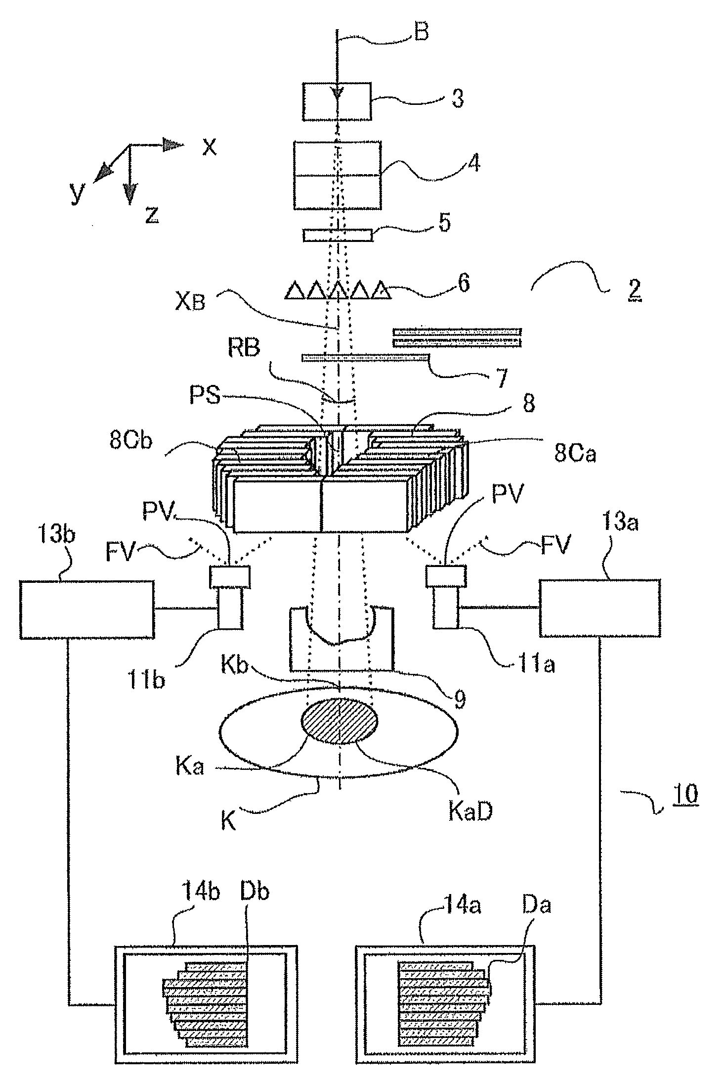
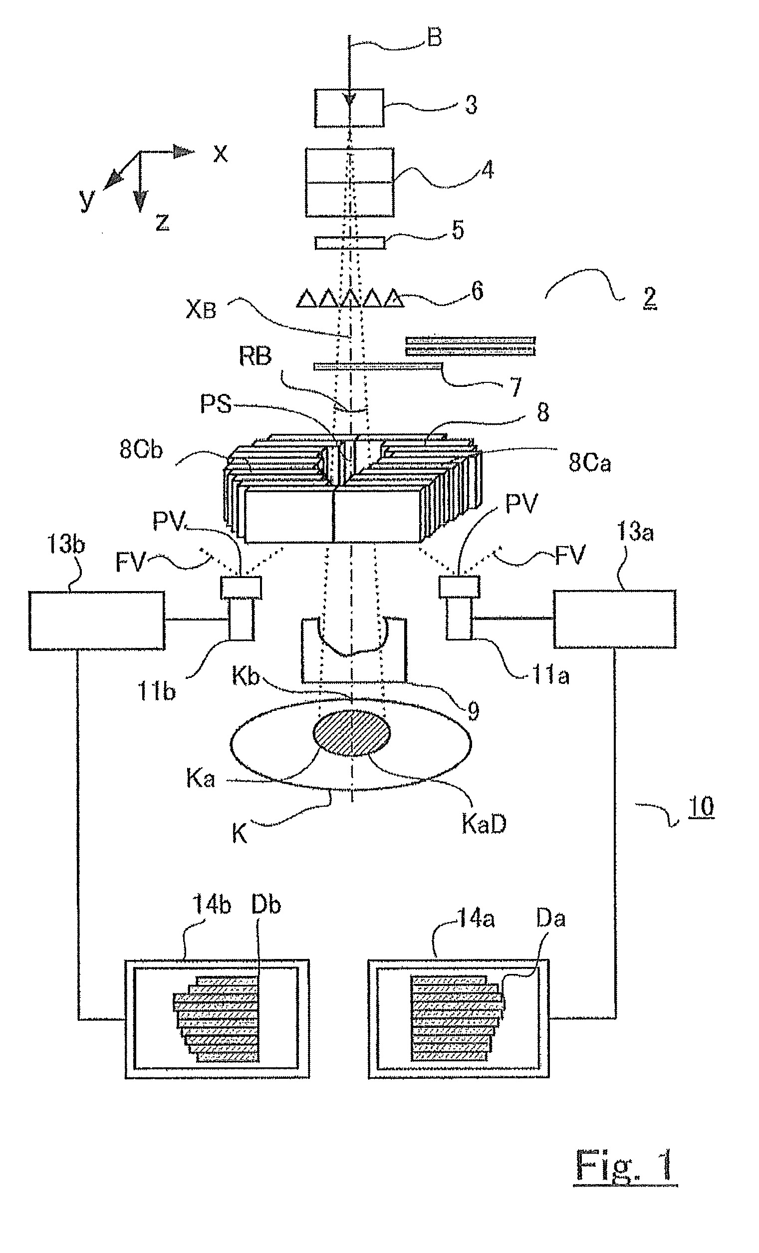
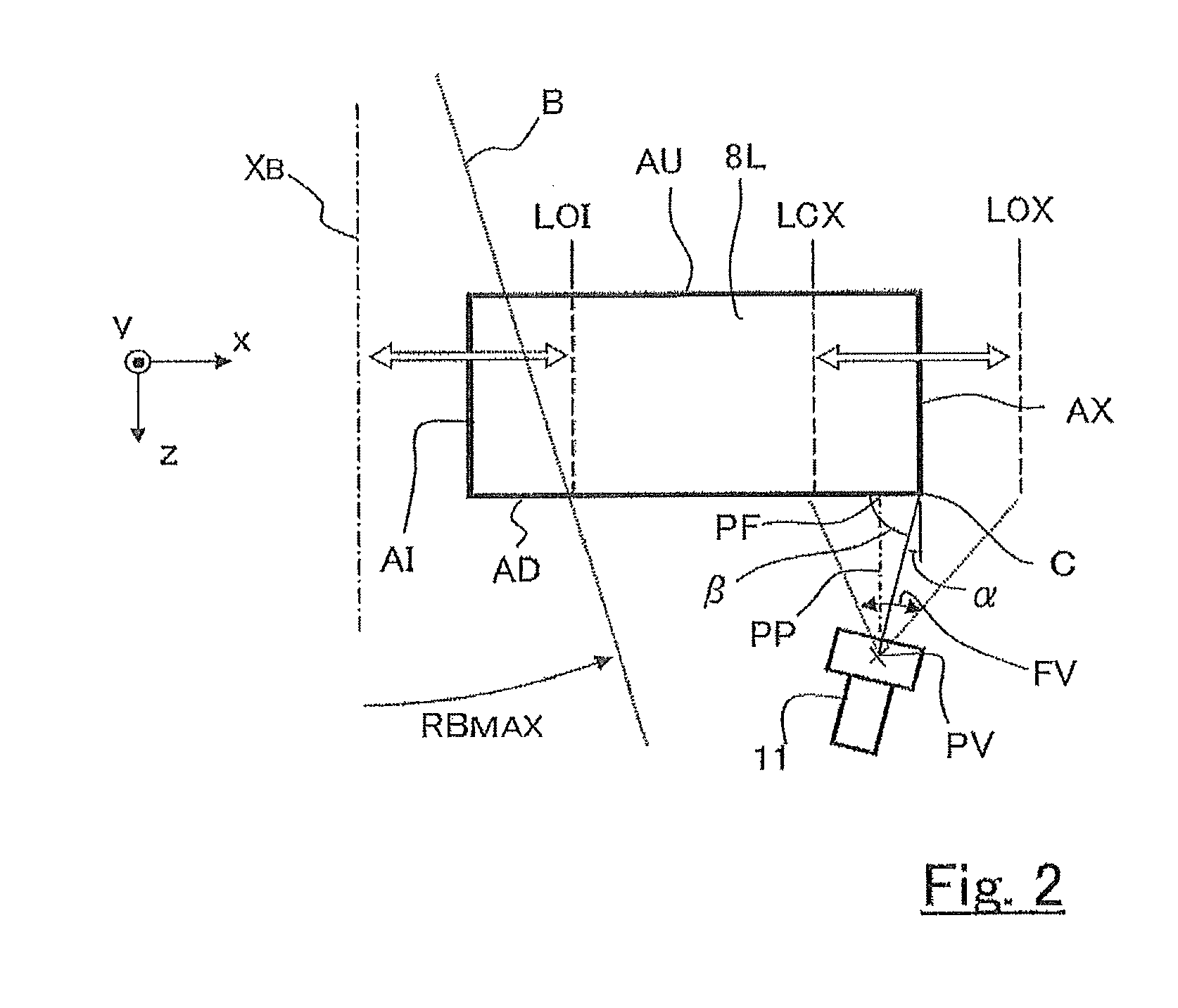
[0019]FIGS. 1 and 2 are diagrams for explaining the configuration of a particle beam therapy system according to Embodiment 1 of the present invention; FIG. 1 is a diagram illustrating the configuration of the whole irradiation system in a particle beam therapy system; FIG. 2 is a diagram illustrating the positional relationship between a multileaf collimator provided in a particle beam therapy system and an image-capturing unit for taking an image of the multileaf collimator. FIG. 3 is a set of diagrams illustrating examples of adjustment of the viewpoint of an image capturing unit (camera) for accurately detecting the position of a leaf, in a particle beam therapy system according to Embodiment 1 of the present invention. FIG. 4 is a set of diagrams for explaining the positional relationship between the leaf plate of a multileaf collimator and the viewpoint of an image-capturing unit in a variant example of particle beam therapy system according to Embodiment 1 of the present inve...

example of embodiment 1

Variant Example of Embodiment 1

[0035]With regard to the relationship between the viewpoint PV and the leaf plate 8L, illustrated in FIG. 3, even in the case where, in addition to Embodiment 1, it is assumed that the orbit is a circumference orbit and the multileaf collimator has a shape such as the outer portion of a sector obtained by simply dividing a ring in the radial direction, there is assumed a basic form in which neighboring side faces (or the tangential lines thereof) cross each other at an angle of 90° and there exists a restriction of α+β=90. Accordingly, in the case where a position where β becomes a right angle is prioritized and, as illustrated in FIG. 3(a), there is performed setting in which the foot PF of the perpendicular line PP drawn from the viewpoint PV is situated in the vicinity of the middle LMX in the driving range of the outer end C, the range where α is positive becomes as narrow as less than the half of the driving range. However, in the case where, as l...

embodiment 2

[0045]In Embodiment 1, there has been described a case where an image is obtained by directly viewing the edge portion C of the downstream side face AD of the leaf plate through the video camera 11; however, in Embodiment 2, there is further provided a mirror; through the mirror, there is taken an image of the edge portion C of the downstream side face AD of the leaf plate 8L.

[0046]FIGS. 5 and 6 are diagrams for explaining the configuration of a particle beam therapy system according to Embodiment 2 of the present invention; FIG. 5 is a diagram illustrating the configuration of the whole irradiation system in a particle beam therapy system; FIG. 6 is a diagram illustrating the positional relationship between a multileaf collimator provided in a particle beam therapy system and a shape monitoring device of the multileaf collimator. FIG. 7 is a set of diagrams for explaining the positional relationship between a leaf plate of a multileaf collimator and a shape monitoring device in a v...


PUM


Abstract

A particle beam therapy system that prevents dispersion of a charged particle beam, reduction of the energy thereof, and upsizing of the system and can accurately monitor the opening shape of a multileaf collimator so as to perform high-accuracy particle beam therapy. An image-capturing unit that takes an image of an outer end of a respective downstream side face of a leaf plate is provided for each row of leaves in such a way as to be situated at a position that is at an outer side of an irradiation field; and adjusted in such a way that a foot of a perpendicular line from a viewpoint, of the image capturing unit, to the downstream side face of a leaf plate, is situated at a position that is at an inner side of the position of the outer end when the leaf plate is maximally driven in the departing direction.

Description

TECHNICAL FIELD[0001]The present invention relates to a particle beam therapy system that performs therapy by irradiating a particle beam onto a diseased site of a patient, and particularly to a particle beam therapy system that can perform irradiation with an irradiation shape conforming to a diseased site, by use of a multileaf collimator.BACKGROUND ART[0002]Some particle beam therapy systems shape an irradiation field through a multileaf collimator so as to irradiate a particle beam in an irradiation shape based on a treatment plan. In such a particle beam therapy system, in the case where during irradiation of a particle beam, the opening shape of the multileaf collimator deviates from the shape specified by a treatment plan, the dose given to a diseased site, which is an irradiation subject, and the distribution of doses differ from the treatment plan; therefore, it is required to rapidly stop the beam irradiation. Accordingly, monitoring, (confirmation) of the leaf positions, ...

Claims


Application Information

Patent Timeline
Patent Type & Authority Patents(United States)
IPC IPC(8): G21K5/04
CPCA61N5/1045G21K1/046A61N2005/1095A61N2005/1087A61N5/1048
Inventor OTANI, TOSHIHIROHAGINO, TAKESHIIKUTA, KOICHI
Owner MITSUBISHI ELECTRIC CORP
Why Eureka
Try Eureka