Exhaust arrangement for an internal combustion engine

a technology for internal combustion engines and exhaust pipes, which is applied in the direction of exhaust treatment, position/direction control, and addition of non-fuel substances to fuel, and achieves the effect of reducing the exhaust back pressur

Active Publication Date: 2013-09-24
LOUGHBOROUGH UNIV
View PDF57 Cites 48 Cited by
  • Summary
  • Abstract
  • Description
  • Claims
  • Application Information

AI Technical Summary

Benefits of technology

[0012]By this arrangement the turbine extracts energy from the exhaust gas during the first, blowdown, exhaust period, and which is used through rotating inertia of the turbine / compressors to drive the compressor to positively extract the exhaust gases from the cylinders, and reduce the exhaust system back pressure and exhaust pumping losses during the second exhaust period. The turbine is also effectively bypassed during the second exhaust period so that it does not increase the exhaust back pressure and exhaust pumping losses. This it has been found leads to significant reductions in pumping losses, improvements in efficiency and fuel economy gains.
[0018]The exhaust arrangement may further comprise a heat exchanger or cooler connected to at least the second exhaust duct for cooling the exhaust gases flowing, in use, through the second exhaust duct. This reduces the exhaust back pressure further. An outlet of the heat exchanger is preferably connected to the inlet of the compressor.

Problems solved by technology

All the prior arrangements have the compressor / pump on one side engine, and turbine on other side engine, or are driven by engine itself with attendant losses.

Method used


Image

  • Exhaust arrangement for an internal combustion engine
  • Exhaust arrangement for an internal combustion engine
  • Exhaust arrangement for an internal combustion engine

Examples


Embodiment Construction

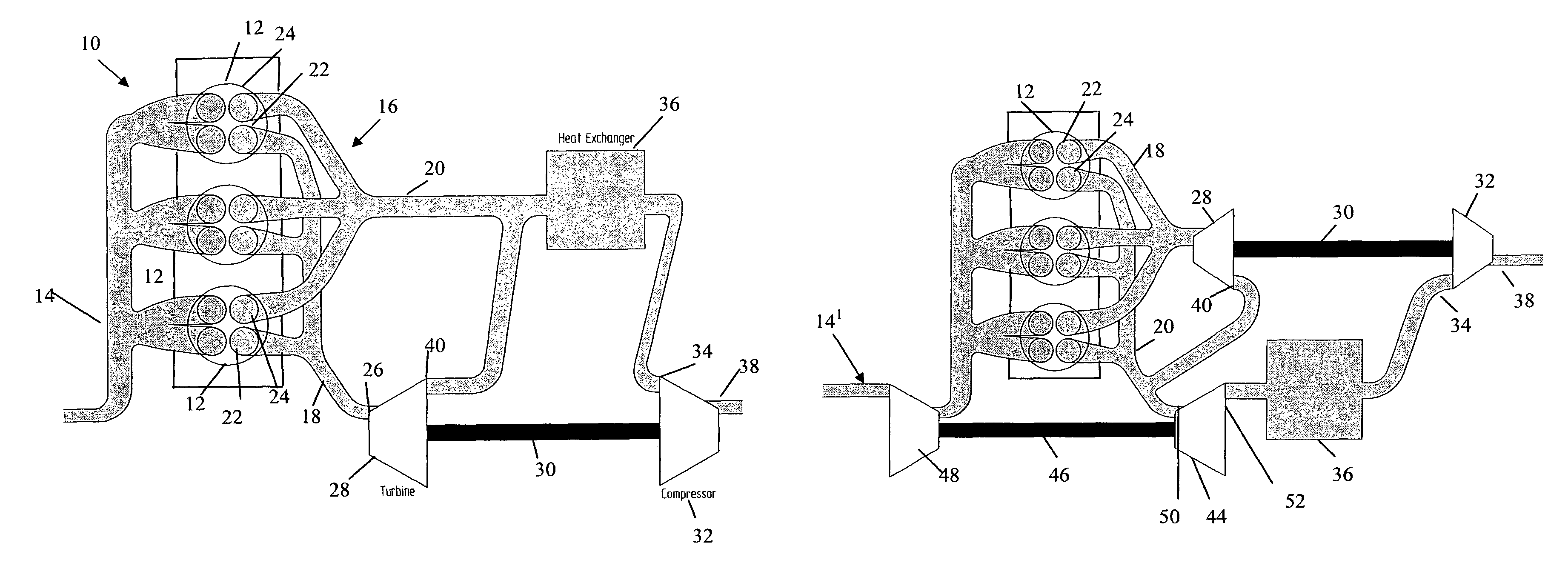
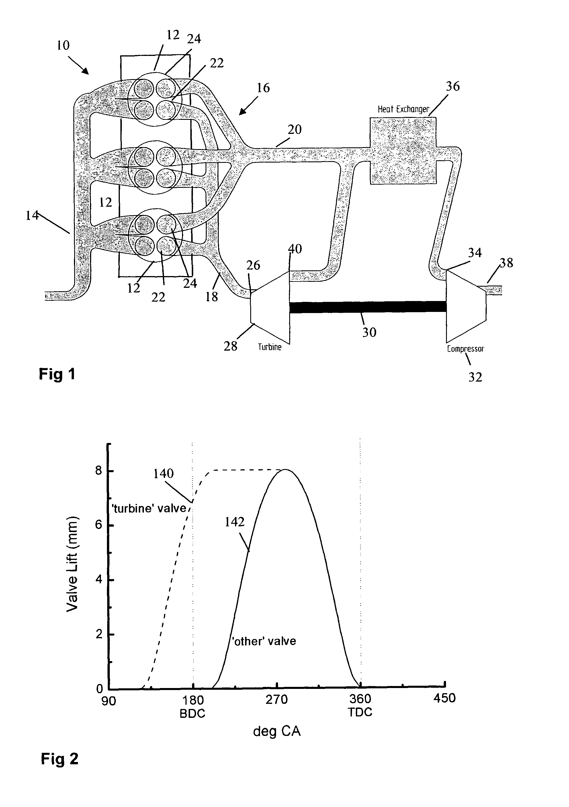
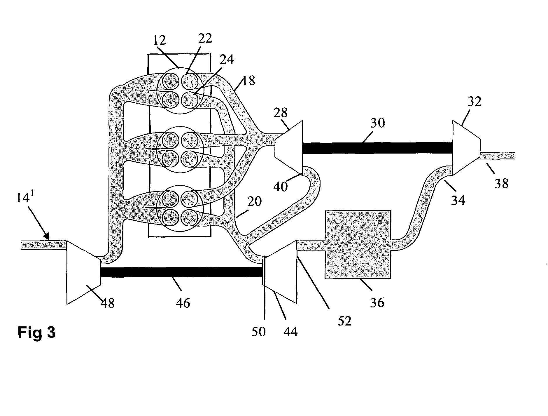
[0026]Referring to FIG. 1 a reciprocating internal combustion engine 10 comprises at least one reciprocating piston (not shown) located within a corresponding cylinder 12 and connected in a conventional manner to rotate a crank shaft (not shown). The movement of the piston within the cylinder 12 defines a swept volume within the cylinder. An inlet arrangement 14 supplies fresh air, a fuel-air mixture or a fuel-air-EGR (exhaust gas recirculation) mixture to each of the cylinders 12 which is then compressed by movement of the piston within the cylinder 12. Combustion then takes place within the cylinder 12 and the expanding gases drive the piston and crank shaft. The combustion gasses are then exhausted from the cylinder 12 and internal combustion engine 10 via an exhaust system 16. The internal combustion engine 10 may have any number of cylinders 12 and corresponding pistons with this particular embodiment the engine 10 having three cylinders 12. The inlet arrangement 14 may compris...


PUM


Abstract

An internal combustion engine including an exhaust arrangement comprises a first exhaust duct and a second exhaust duct. A valve arrangement preferably comprising separate first and second exhaust valves associated with each cylinder, to selectively direct exhaust from engine to the first exhaust duct during a first exhaust period, and to the second exhaust duct during a subsequent second exhaust period. A turbine having an inlet is connected to the first exhaust duct; and a compressor drivingly connected to and driven by the turbine, has an inlet connected to second duct. The compressor, driven by the turbine extracting energy from the exhaust, reduces the back pressure in the exhaust system reducing pumping losses, with the second duct bypassing the turbine in the second exhaust period such that the turbine also does not increase the exhaust back pressure at least during the main second exhaust phase.

Description

BACKGROUND OF THE INVENTION[0001]1. Field of the Invention[0002]The present invention relates to internal combustion engines, in particular to an exhaust arrangement for a reciprocating or rotary internal combustion engine.[0003]2. Related Art[0004]There is a continuing need to improve the efficiency and fuel economy of modern internal combustion engines. One area of inefficiency relates to the ‘breathing’ of the engine. During the ‘breathing’ of the engine the piston does work to draw the fresh air or air-fuel mixture into the cylinder and then expel it after the compression and power strokes. This breathing takes work (known as pumping losses) directly from the output of the engine and, hence, is detrimental to the fuel economy of the engine (more notably on throttled engines). Much effort is being put into operating the engine with minimal pumping losses to improve fuel economy.[0005]To operate more efficiently modern engines may be ‘boosted’ by an inlet compressor which may be d...

Claims


Application Information

Patent Timeline
Patent Type & Authority Patents(United States)
IPC IPC(8): F02B33/00F02B37/007F02B75/02F02B37/00F01N5/04F02M25/07
CPCF01N5/02F01N13/107F02B37/001F02B37/004F02B37/18F02D13/0249F02D13/0257F02B37/02F01N2290/06Y02T10/18Y02T10/144Y02T10/16Y02T10/12F02B35/02F02D13/0242F01N13/08
Inventor WILLIAMS, ANDREW MORGAN
Owner LOUGHBOROUGH UNIV
Why Eureka
Try Eureka