Fuel supplying apparatus for internal combustion engine

a technology for internal combustion engines and fuel supply apparatuses, which is applied in the direction of combustion engines, machines/engines, charge feed systems, etc., can solve the problems of reducing the capacity of the fuel tank, not an advisable solution, and often limited unit as a whole, so as to increase the air flow resistance increase the pressure loss of the purge path as a whole.

Active Publication Date: 2013-09-24
HONDA MOTOR CO LTD
View PDF16 Cites 3 Cited by
  • Summary
  • Abstract
  • Description
  • Claims
  • Application Information

AI Technical Summary

Benefits of technology

[0009]It is therefore an object of the present invention to provide an apparatus that is capable of suppressing intrusion of oil mist into a negative pressure introducing inlet of an automatic cock, increasing the degree of freedom of disposition of a fuel supplying apparatus, and sufficiently securing the capacity of a fuel tank.
[0013]In addition, according to the present invention, the point at which the purge path branches from the negative pressure communication path is set to be at the lowest position of the negative pressure communication path such that the point is able to collect the oil mist that intrudes from the crankcase. Even if the oil mist intrudes from the crankcase into the negative pressure communication path, the oil mist intruding gathers at the lowest position of the negative pressure communication path. Therefore, even when the automatic cock is not disposed above the crankcase, the intrusion is able to be suppressed of the oil mist into the negative pressure introducing inlet of the automatic cock. As above, the automatic cock does not need to be disposed above the crankcase and, therefore, the positions of the automatic cock and the fuel tank are able to arbitrarily be set at positions at which no thermal influence is received that is caused by the heat dissipation from the internal combustion engine. Therefore, the degree of freedom of disposition of the fuel tank and the fuel supplying apparatus is able to be increased.
[0015]Preferably, a point at which the purge path is connected to the air cleaner is positioned at a position that is lower than the point at which the purge path branches. Therefore, the oil mist gathering at the lowest position of the negative pressure communication path enters the air cleaner passing through the purge path due to the gravity. The oil mist entering the air cleaner is combusted in the combustion chamber. As a result, the intrusion of the oil mist into the negative pressure introducing inlet of the automatic cock can further be suppressed.
[0016]Desirably, the purge path has an air flow resistance increasing unit in the vicinity of the point at which the purge path branches, and the air flow resistance increasing unit is adapted to set air flow resistance of the purge path to be higher than air flow resistance of the negative pressure communication path. The pressure loss of the purge path as a whole is increased by increasing the air flow resistance of the purge path by the air flow resistance increasing unit as above. As a result, at the branching point, the pressure difference is able to be set to be an optimal value between the internal pressure of the negative pressure communication path and the internal pressure of the purge path. Because the pressure difference is suitable, the negative pressure state in the negative pressure communication path is not offset by the pressure of the air that flows from the purge path to the negative pressure communication path. The negative pressure in the negative pressure communication path is able to sufficiently be secured that acts to open the automatic cock and, therefore, the automatic cock is able to suitably be operated to open and close.

Problems solved by technology

Oil mist and blowby gas produced in the crankcase are caused to circulate from the crankcase to the intake system and, thereby, are combusted in a combustion chamber.
Especially, for a configuration that has an internal combustion engine and a fuel supplying apparatus incorporated as one unit such as, for example, a small sound-proof engine-driven generator, the height of the unit as a whole is often limited.
However, this result in reducing the capacity of the fuel tank and, therefore, this is not an advisable solution.

Method used


Image

  • Fuel supplying apparatus for internal combustion engine
  • Fuel supplying apparatus for internal combustion engine
  • Fuel supplying apparatus for internal combustion engine

Examples


Embodiment Construction

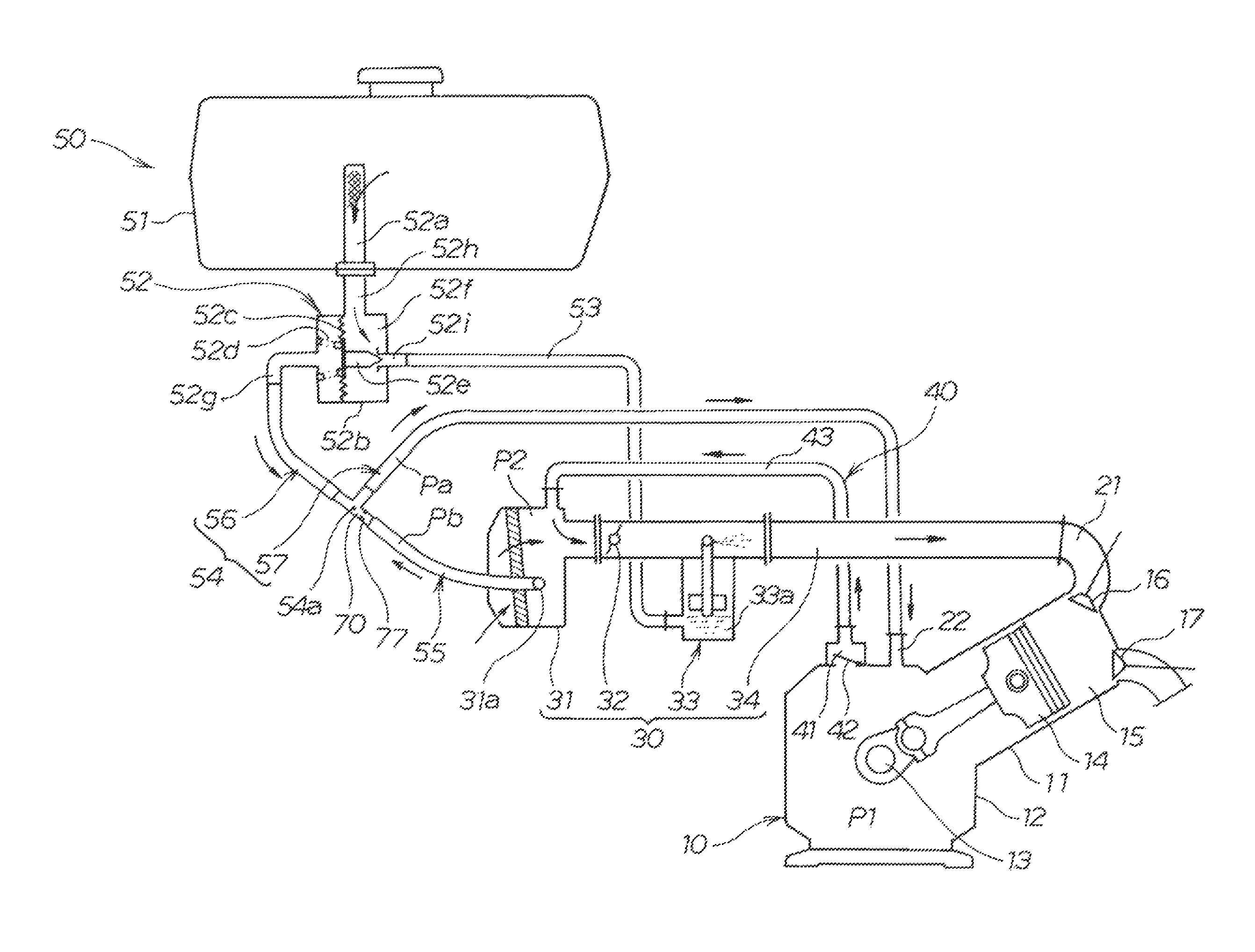
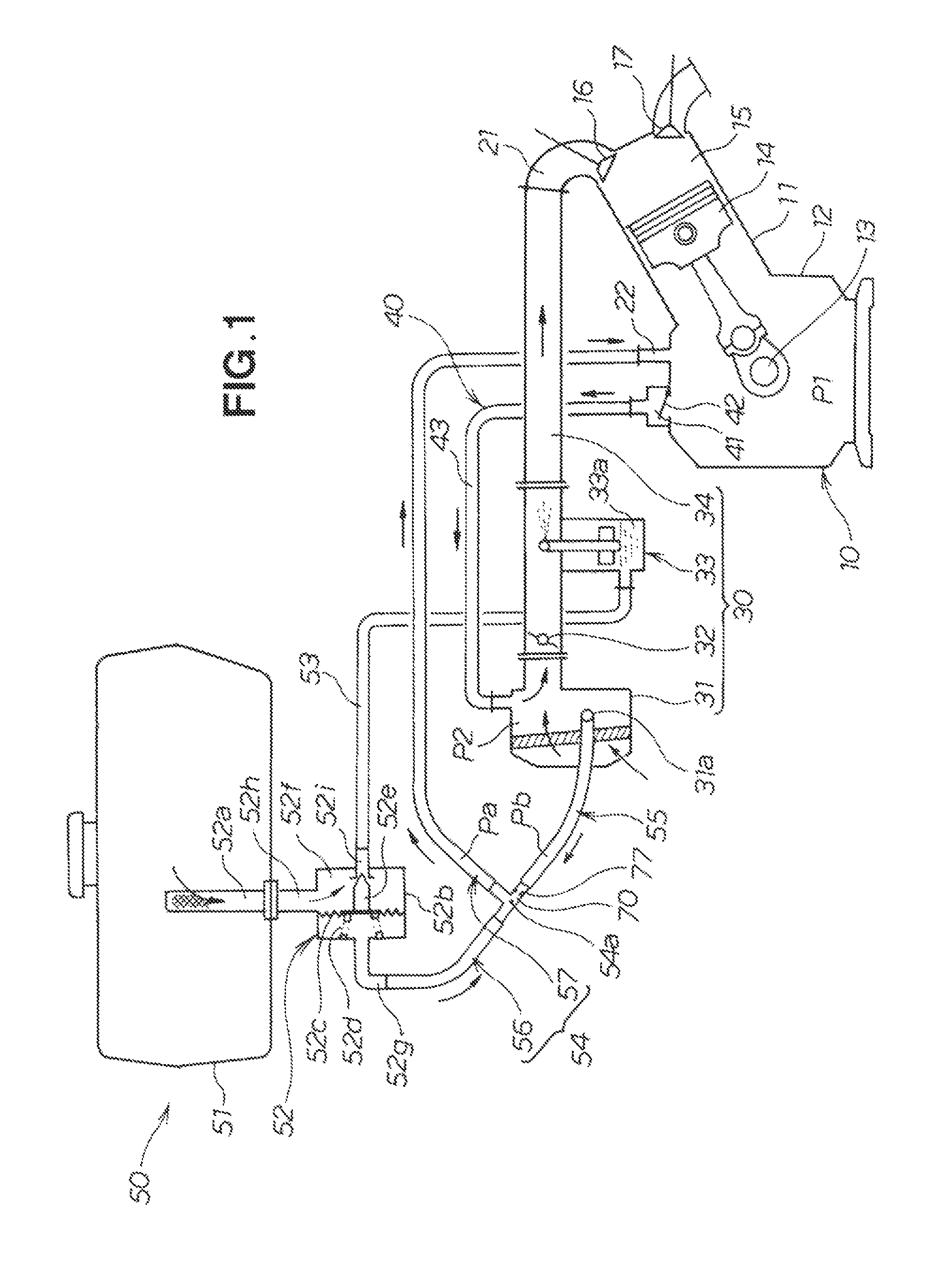
[0024]An internal combustion engine 10 depicted in FIG. 1 includes, for example, a transverse single-cylinder four-cycle engine. The internal combustion engine 10 includes: a crankcase 12 that integrally has a cylinder 11, a crank shaft 13, a piston 14, a combustion chamber 15, an intake valve 16, and an exhaust valve 17. The crank shaft 13 is horizontally disposed. The cylinder 11 is inclined upward.

[0025]An intake system 30 for the internal combustion engine 10 includes an air cleaner 31, a throttle valve 32, a carburetor 33, and an intake pipe 34. The carburetor 33 has a float chamber 33a that temporarily retains fuel. The intake pipe 34 is connected to an intake inlet 21 of the internal combustion engine 10.

[0026]In the internal combustion engine 10, a portion of combustion gas produced in the combustion chamber 15 leaks from a point between the cylinder 11 and the piston 14 into the crankcase 12. The combustion gas leaking is referred to as “blowby gas”. The blowby gas includes...


PUM


Abstract

A fuel supplying apparatus is disclosed that suppresses intrusion of oil mist into a negative pressure introducing inlet of an automatic cock and that, thereby, improves the degree of freedom of disposition. The negative pressure introducing inlet of the automatic cock is connected to a crankcase through a negative pressure communication path. The automatic cock is opened by a negative pressure generated in the crankcase and, thereby, a fuel supply path is opened that is for supplying fuel from a fuel tank to an internal combustion engine. The negative pressure communication path communicates with the air cleaner through a purge path that branches from the negative pressure communication path at a halfway point of the negative pressure communication path. The point at which the purge path branches from the negative pressure communication path is set to be at the lowest position of the negative pressure communication path to be able to collect the oil mist intruding from the crankcase.

Description

FIELD OF THE INVENTION[0001]The present invention relates generally to an apparatus for supplying fuel to an internal combustion engine and, more particularly, to a technique of opening a fuel supply path by using a negative pressure in a crankcase.BACKGROUND OF THE INVENTION[0002]Schemes of supplying fuel from a fuel tank to an intake system of an internal combustion engine includes a scheme of supplying fuel by using a fuel pump and a scheme of supplying fuel by using the gravity. According to the scheme of supplying fuel by using the gravity, a fuel tank is disposed above a carburetor and the fuel is supplied from the fuel tank to the carburetor. This scheme employs a relatively simple configuration and is often used.[0003]According to the scheme of supplying fuel by using the gravity, an automatic cock is disposed in a fuel supply path to introduce the fuel from the fuel tank to the carburetor. The automatic cock is a valve that opens the fuel supply path by using a negative pre...

Claims


Application Information

Patent Timeline
Patent Type & Authority Patents(United States)
IPC IPC(8): F02B25/06F01M11/08
CPCF02M37/0017F02M37/20F02M37/02
Inventor KOBAYASHI, TAKAO
Owner HONDA MOTOR CO LTD
Why Eureka
Try Eureka