Separator with pedal

a pedal and separator technology, applied in the field of conveyers, can solve the problems of limited average height of the trigger pedal and less vulnerable of the trigger pedal during long-term use, and achieve the effects of less vulnerable, easy exchange, and less expensiv

Active Publication Date: 2013-10-01
INTERROLL HLDG
View PDF11 Cites 1 Cited by
  • Summary
  • Abstract
  • Description
  • Claims
  • Application Information

AI Technical Summary

Benefits of technology

[0013]Compared to the trigger pedals known by the state of the art, the trigger pedal of the conveyor according to the invention is arranged at a limited height in its active position compared to the known trigger pedals, since only one end of the trigger pedal protrudes into the conveying area while the other end will stay out of the conveying area. This results in a limited average height of the trigger pedal that causes the trigger pedal to be less vulnerable during long-term use.
[0014]Also, such a trigger pedal forms a very compact part of the conveyor, wherein a damaged trigger pedal can easily be exchanged and is less expensive than the known trigger pedals.
[0015]Also, the untiltable end of the trigger pedal can be fixed to the frame of the conveyor like the other rollers, while only the tiltable end of the trigger pedal needs a special tiltable end. This provides a financial and an assembly advantage over the state of the art, since the special tiltable mounts usually require more parts and are more complicated to assemble.
[0016]The fixation of one end of the trigger pedal with the frame of the conveyor provides an improved stability.
[0020]In an embodiment, the trigger pedal is arranged parallel to the plurality of rollers in the triggered position. Thus, it can have the function of a roller in its triggered position, since this is the position a load will usually be pressing the trigger pedal down to. This is especially advantageous when the trigger pedal is a single roller. Then, the trigger pedal in form of a roller is arranged so that it can rotate in conveying direction when it is in its triggered position.

Problems solved by technology

This results in a limited average height of the trigger pedal that causes the trigger pedal to be less vulnerable during long-term use.

Method used


Image

  • Separator with pedal
  • Separator with pedal
  • Separator with pedal

Examples


Embodiment Construction

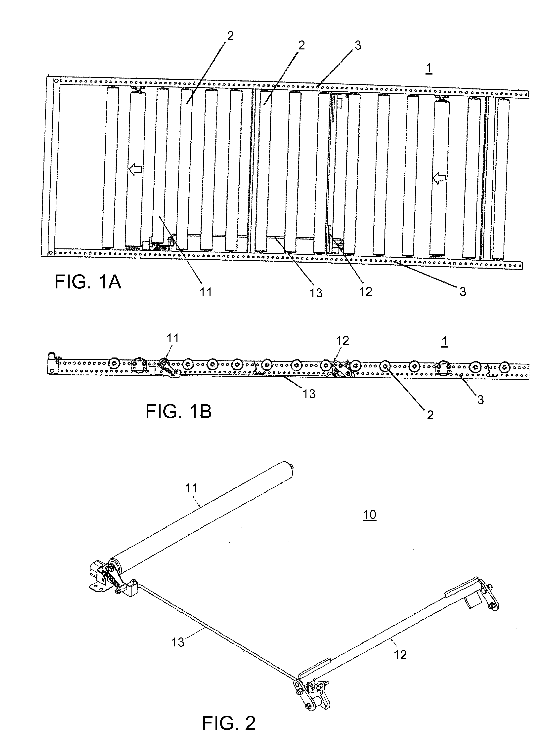
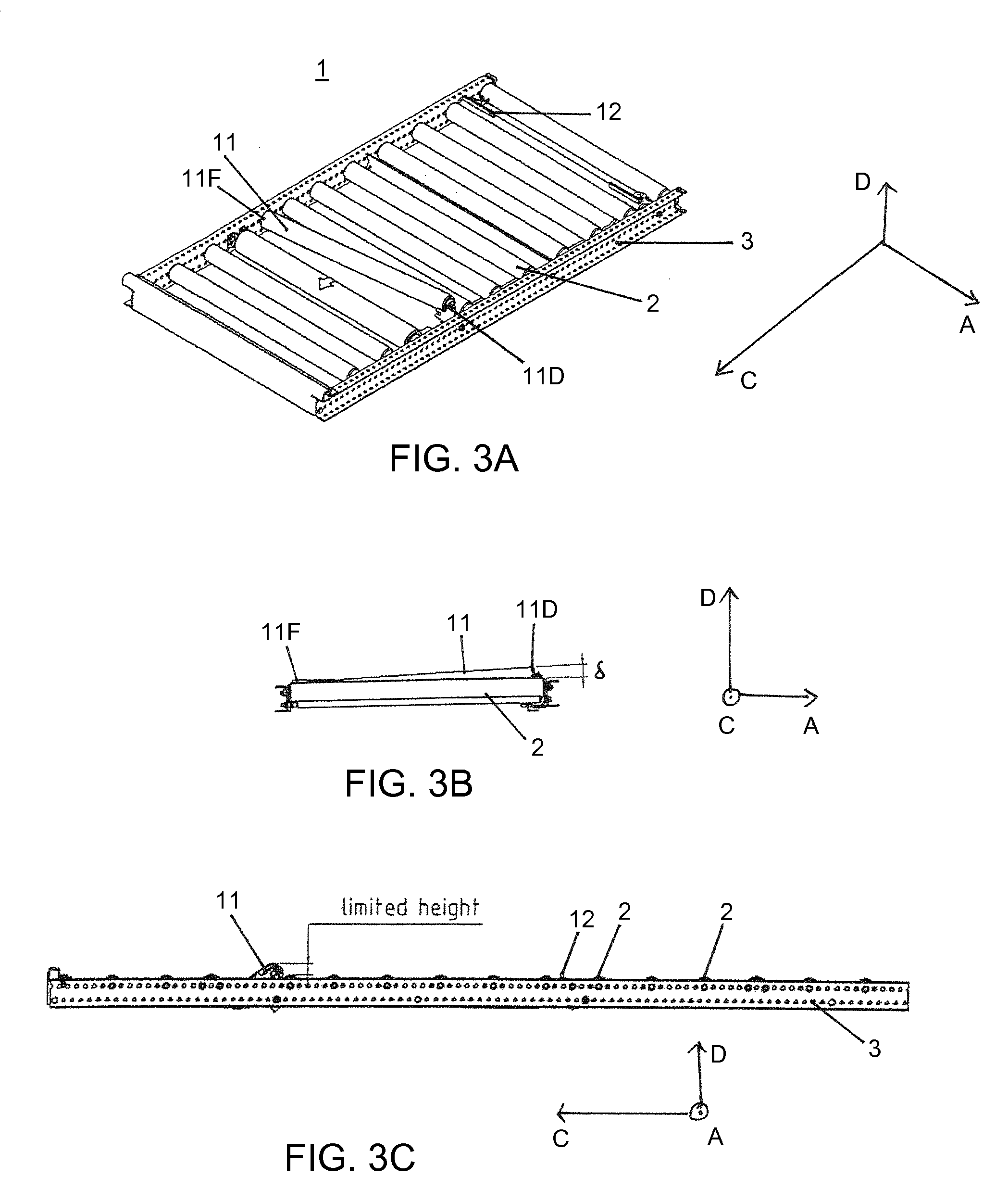
[0029]FIG. 1A shows a diagrammatic top view of a conveyor 1 that can be used as storage chute in dynamic storage facilities. Two beams 3 are arranged parallel to each other in a direction by which loads or goods can be transported. They form a frame and the side boundary of the conveyor and comprise a fixed position. Multiple rollers or cylinders 2 are arranged substantially perpendicular to the beams 3 to carry and transport goods or loads (goods or loads not shown in FIG. 1A). The rollers 2 are mounted rotatable around their axes to transport the loads.

[0030]Some of the rollers 2 (in FIG. 1A the rollers marked with an arrow) are driven by an engine (not shown) to rotate around their axes and, thus, moving the loads downstream on the conveyor.

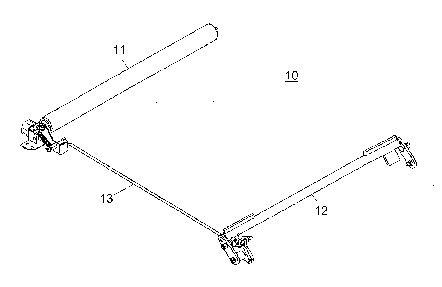
[0031]FIG. 1A also shows parts of a separator device 10, especially a trigger pedal 11 of the separator device, a separator stop 12, and a coupling 13 to couple the trigger pedal 11 with the stop 12. The trigger pedal 11 consists of a single r...


PUM


Abstract

A conveyor for conveying loads along a conveying direction includes a frame (3) arranged in the conveying direction, a plurality of rollers (2) mounted in the frame (3) rotatable in the conveying direction (C), a trigger pedal (11) movable between an active position and a triggered position, a separator stop (12), and a coupling (13) between the trigger pedal (11) and the separator stop (12) for transmitting a movement applied to the trigger pedal (11) to the separator stop (12). The trigger pedal (11) is one-sided tiltable out of a substantially parallel to the rollers (2) arranged position.

Description

BACKGROUND OF THE INVENTION[0001]1. Field of the Invention[0002]The invention relates to a conveyor comprising a trigger pedal for a separator stop.[0003]2. Description of the Related Art[0004]Conveyors are commonly used for the storage of pallets or boxes in gravity or dynamic storage. Dynamic storage facilities are made of chutes fitted with rollers or cylinders mounted parallel to one another on beams forming a frame which is tilted from its upstream to its downstream section. These rollers and / or cylinders determine a raceway on which the loads, generally handling pallets, are placed for storage.[0005]In order to suppress the problems associated with the extraction of the loads located at the lower portion of the storage chute, and notably that of the pressure exerted onto the end load by the accumulation of the upstream loads, a load separator device is commonly used at the level of the downstream end of the chute. This device is suited to isolate at least the first load, locat...

Claims


Application Information

Patent Timeline
Patent Type & Authority Patents(United States)
IPC IPC(8): B65G13/06
CPCB65G47/261B65G1/08
Inventor SEJOURNE, JEROME
Owner INTERROLL HLDG
Why Eureka
Try Eureka