Drill bit

a drill bit and drill bit technology, applied in the field of drill bits, can solve the problems of high torque and significant speed requirements, and achieve the effect of smoothering the interior wall

Inactive Publication Date: 2013-10-01
BURN STEVE
View PDF16 Cites 7 Cited by
  • Summary
  • Abstract
  • Description
  • Claims
  • Application Information

AI Technical Summary

Benefits of technology

[0035]Advantageously, the recesses are adapted to be grasped by the chuck to prevent the drill bit falling out.
[0040]This provides an easy and speedy change-over to the required bit format without the risk of the bit slipping while in use.
[0042]This may provide better coupling when drilling through a surface and allows better transfer of power through torque.
[0045]This enables the cutter to leave a ‘cleaner’ hole and a smoother interior wall thereof.

Problems solved by technology

They are not designed to undergo high torques or stresses, and have changed little since those bits used with hand-powered drills or in a bit and brace.
However, there are many circumstances in which a tradesman or a DIY operator might wish to cut relatively large holes in wood, but with speed being a significant requirement.

Method used


Image

  • Drill bit
  • Drill bit
  • Drill bit

Examples


Embodiment Construction

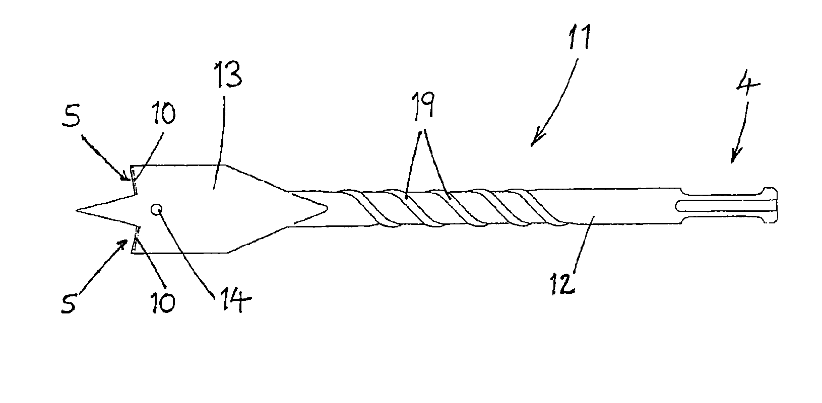
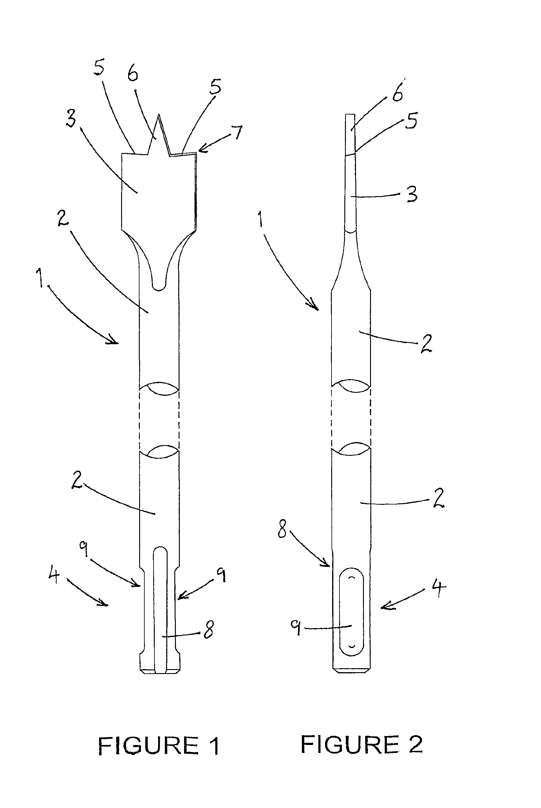
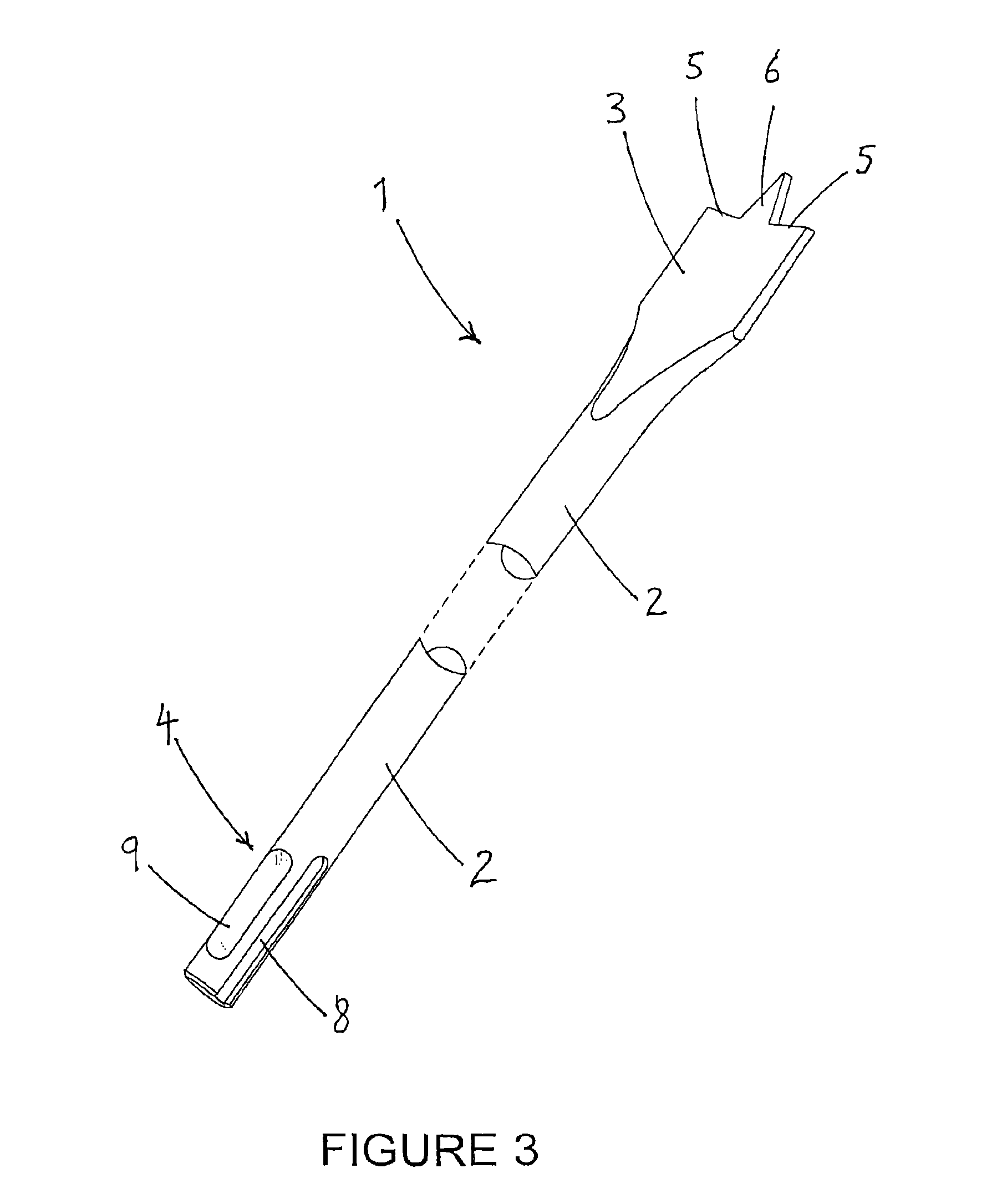
[0055]Referring now to the Figures and to FIG. 1 in particular, a first drill bit 1 comprises an elongate cylindrical shaft 2 having at a first, distal end a cutting spade portion 3 (or paddle) and at a second, proximal end a shank portion 4 adapted to be received by a drill chuck.

[0056]The cutting spade portion 3 has two distal cutting edges 5, one extending to each side of a wedge-shaped centring point 6, which extends distally along a longitudinal axis of the drill bit 1. Each cutting edge 5 extends at a slight angle to a normal to said longitudinal axis, such that its outer tip 7 is raked forwardly (other embodiments, not shown, are provided with small distally-extending spurs at each outer tip 7).

[0057]The cutting spade portion 3 thus has similarities with a conventional spade bit or paddle bit, although as shown in FIG. 2 the flat spade portion 3 is made thicker and more robust than a conventional wood bit of the above type.

[0058]The shaft 2 is also significantly more robust t...


PUM

PropertyMeasurementUnit
operating lengthaaaaaaaaaa
sizesaaaaaaaaaa
sizesaaaaaaaaaa

Abstract

A drill bit for drilling holes in wood or the like has a spade cutting element, a thick elongate shaft and a shank adapted to be inserted into an SDS drill chuck. In a preferred embodiment, the shaft is provided with one or more ridges extending helically along most of its length, to strengthen and stiffen the shaft and to direct drilling debris away from the cutting element. The shaft has a diameter greater than or equal to that of the shank. The drill bit may be installed in and removed from the drill chuck more rapidly than conventional wood bits, is more robust and is more convenient and reliable in use.

Description

CROSS REFERENCE TO RELATED APPLICATIONS[0001]This is a U.S. National Phase application of PCT / GB2008 / 003268, filed on Sep. 26, 2008 and published in English as WO2009 / 040540 on Apr. 2, 2009, which claimed priority to GB Application No. 0718758.6, filed on Sep. 26, 2007.BACKGROUND ART[0002]The present invention relates to a drill bit. More particularly, but not exclusively, it relates to an exchangeable drill bit for use with an electrically-powered hand drill to form holes in wood or similar materials.[0003]It is well known for drill bits to have substantially cylindrical proximal ends adapted to be inserted into a drill chuck. It is also known to provide drill bits that have proximal ends which are non-cylindrical. (The proximal end, known as the ‘shank’, is the part of a drill bit gripped by the chuck of a drill). Different types of shank / chuck combination deliver different balances of performance, such as allowing higher torque or greater centering accuracy. Known shank types inc...

Claims


Application Information

Patent Timeline
Patent Type & Authority Patents(United States)
IPC IPC(8): B27G15/00
CPCB23B51/0009B23B51/02B25D17/088B27G15/00B25D2222/75Y10T408/9097Y10T408/907Y10T408/9065Y10T408/899B23B51/00035B25D17/02
Inventor BURN, STEVE
Owner BURN STEVE
Why Eureka
Try Eureka