
Visible light activatable photocatalyst

a photocatalyst and visible light technology, applied in the field of photocatalysts, can solve the problems of unsuitable ultraviolet light activation photocatalysts, and achieve the effects of low cost energy efficiency, reduced band gap of crystalline materials, and reduced band gap energy of nanoporous crystalline materials produced by this method

Active Publication Date: 2013-10-08
KASTUS TECHNOLOGIES DESIGNATED ACTIVITY COMPANY
View PDF8 Cites 13 Cited by
  • Summary
  • Abstract
  • Description
  • Claims
  • Application Information

AI Technical Summary

Benefits of technology

[0023]The invention further provides use of microwave irradiation to crystallise a suspension of an inorganic or organic precursor of a nanoporous crystalline material under suitable conditions in a process for the formation a nanoporous crystalline material with a low energy band gap. The conditions suitable to crystallise the material may be non-pressurised conditions. The band gap energy of the nanoporous crystalline material may be reduced to allow electron excitation by light in the visible region of the electromagnetic spectrum. The nanoporous crystalline material may comprise titanium. A dopant material may be present as crystallisation occurs. The dopant material may reduce the band gap of the crystalline material. The nanoporous crystalline material may be a visible light active photocatalyst. The nanoporous crystalline material may have a surface area between about 100 m2 / g and about 400 m2 / g. The nanoporous crystalline material may have a surface area between about 150 m2 / g and about 350 m2 / g such as between about 200 m2 / g and about 300 m2 / g.
[0030]3. This process takes less time compared to conventional methods.
[0033]The low energy requirements of the method, the safety and low cost associated with operating the method at ambient pressure and the environmentally friendly nature of the process all combine to make the process very attractive from an industrial scale-up perspective.
[0045]In a further aspect, the band gap of the crystalline materials may be reduced through doping as hereinbefore described. Desirably, the band gap energy of the nanoporous crystalline materials produced by this method may be reduced to allow electron excitation by light in the visible region of the electromagnetic spectrum. Thus, materials produced by this low cost energy efficient process may be suitable as visible light active photocatalysts.

Problems solved by technology

Such UV activatable photocatalysts are not suitable, for use under ambient (visible) light conditions.

Method used


Image

  • Visible light activatable photocatalyst
  • Visible light activatable photocatalyst
  • Visible light activatable photocatalyst

Examples


example 1

Microwave Assisted (Low Temperature) Synthesis of Nanocrystalline TiO2

Experimental

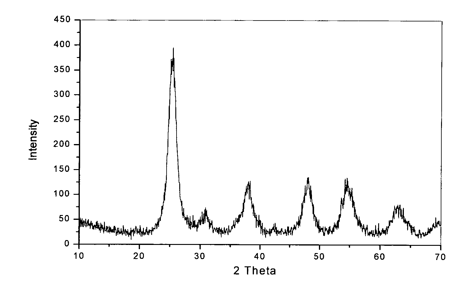
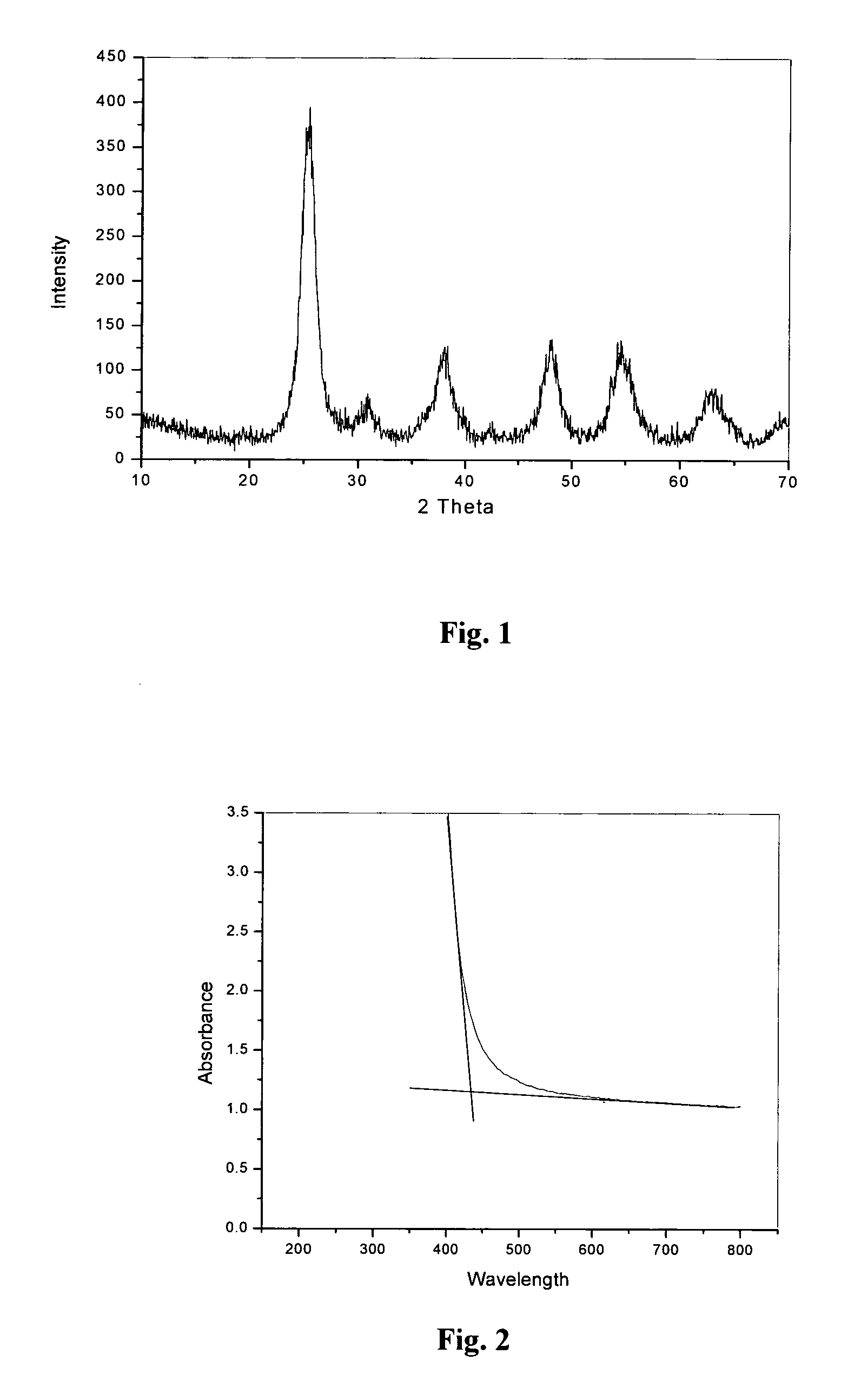
[0098]7.5 ml of titanium (IV) isopropoxide was added to 75 ml boiling water with constant stirring (volume ratio between TTIP and water was fixed as 1:10 in all preparations). Precipitated hydrated titanium oxide were stirred for 30 minutes, and treated with microwave radiations of power 300 W for 60 minutes. It was then filtered, dried in an oven at 80° C. to form a powder. An X-ray diffraction pattern of the powder is given in FIG. 1.

X-Ray Diffraction Studies

[0099]High intensity broad peaks in the X-ray diffraction pattern indicate the formation of nanocrystalline anatase titania. The average crystallite size D was 6.1 nm determined according to the Scherrer equation D=Kλ / β cos θ where k is a constant (shape factor, about 0.9); 1 is the X-ray wavelength; β is the full width at half-maximum of the diffraction line and θ is the diffraction angle. The values of β and θ are from the anatase (1 0 1) diff...

example 2

Microwave Assisted Synthesis of Phosphoric Acid Modified Titania

[0102]Phosphoric acid modified nanocrystalline titania powder was prepared by a microwave assisted method in an open container using a very low power (300 W) for 60 min. Molar ratios between titanium isopropoxide and phosphoric acid used were 1:0 (undoped / control), 1:0.05, 1:0.1, 1:0.15, 1:0.2, and 1:0.25.

Experimental

[0103]7.5 ml of titanium (IV) isopropoxide was added to 75 ml boiling water containing phosphoric acid with constant stirring. Precipitated hydrated titanium oxide were stirred for 30 minutes, and treated with microwave radiations of power 300 W for 60 minutes. It was then washed, dried in an oven at 80° C. and powdered well. X-ray diffraction pattern was then taken of the powder. This was repeated with the respective ratios of titanium isopropoxide:phosphoric acid as set above. The respective UV spectra of the powders are set out in FIG. 5. The top trace in FIG. 5 represents an undoped control. Each succes...

example 3

Microwave Assisted Synthesis of Iron Doped Titania

[0107]Iron doped nanocrystalline titania powder was prepared by a microwave assisted method in an open vessel (100 ml glass beaker) using a very low power (300 W) for 60 min. Molar ratios between titanium isopropoxide and iron precursor used were 1:0, 1:0.005, 1:0.01, 1:0.025, 1:0.05, 1:0.1 and 1:0.5.

Experimental

[0108]7.5 ml of titanium (IV) isopropoxide was added to 75 ml boiling water containing different amounts of ferric chloride (as iron source) with constant stirring. Precipitated hydrated titanium oxide was stirred for 30 minutes, and treated with microwave radiations of power 300 W for 60 minutes. These materials were then washed, dried in an oven at 80° C. and powdered well. X-ray diffraction pattern of the powders are given in FIG. 11. The top trace in FIG. 11 represents an undoped control. Each successive trace (moving from top to bottom) represents respectively the spectrum for the 1:0.005, 1:0.01, 1:0.025, 1:0.05, 1:0.1 ...


PUM

PropertyMeasurementUnit
band gapaaaaaaaaaa
crystallite sizeaaaaaaaaaa
crystalline sizeaaaaaaaaaa

Abstract

A visible light activatable mesoporous titanium dioxide photocatalyst having a surface area of from 100 m2 / g to 400 m2 / g. The photocatalyst may have a rate of decomposition greater than 0.005 min−1. The photocatalyst may have a band gap width less than 2.95 eV. The photocatalyst may comprise undoped titanium dioxide or doped titanium dioxide. A hydrothermal process for synthesising a photocatalyst is also described.

Description

[0001]This is a national stage of PCT / IE09 / 000008 filed Mar. 9, 2009 and published in English, which has a priority of United Kingdom no. 0804365.5 filed Mar. 10, 2008, hereby incorporated by reference.[0002]The invention relates to a photocatalyst. In particular the invention relates to a visible light activatable photocatalyst.[0003]Commercially available titanium dioxide photocatalysts are know such as Degaussa P25 (a titanium dioxide photocatalyst comprising 75% anatase phase titanium dioxide and 25% rutile, phasae titanium dioxide), however these photocatalysts are activated by ultraviolet light (light with a wavelength under 400 nm) irradiation. Such UV activatable photocatalysts are not suitable, for use under ambient (visible) light conditions.STATEMENTS OF INVENTION[0004]According to the invention there is provided a visible light activatable mesoporous titanium dioxide photocatalyst having a surface area of from 100 m2 / g to 400 m2 / g. The photocatalyst may have a surface ar...

Claims


Application Information

Patent Timeline
Patent Type & Authority Patents(United States)
IPC IPC(8): B01J37/34B01J23/00C01G23/047
CPCB01J21/063B01J35/004B01J35/1019B01J35/1061B01J37/0215B01J37/346B82Y30/00C01G23/047C01G23/053B01J23/745B01J27/12B01J27/16B01J27/24C01P2002/52C01P2002/72C01P2002/82C01P2002/84C01P2004/64C01P2006/12C01P2006/16
Inventor ETACHERI, VINODKUMARPILLAI, SURRESH C.COLREAVY, JOHN
Owner KASTUS TECHNOLOGIES DESIGNATED ACTIVITY COMPANY
Learn More