Digital phase-locked loop apparatus using frequency shift keying and method of controlling the same

a phase-locked loop and digital technology, applied in the direction of electrical apparatus, pulse automatic control, delta modulation, etc., can solve the problems of increasing current consumption, increasing time and cost, and reducing the use of transceivers capable of reducing power consumption in wireless communication and being flexibly used in many applications, so as to facilitate fsk

Inactive Publication Date: 2013-10-08
ELECTRONICS & TELECOMM RES INST +1
View PDF7 Cites 8 Cited by
  • Summary
  • Abstract
  • Description
  • Claims
  • Application Information

AI Technical Summary

Benefits of technology

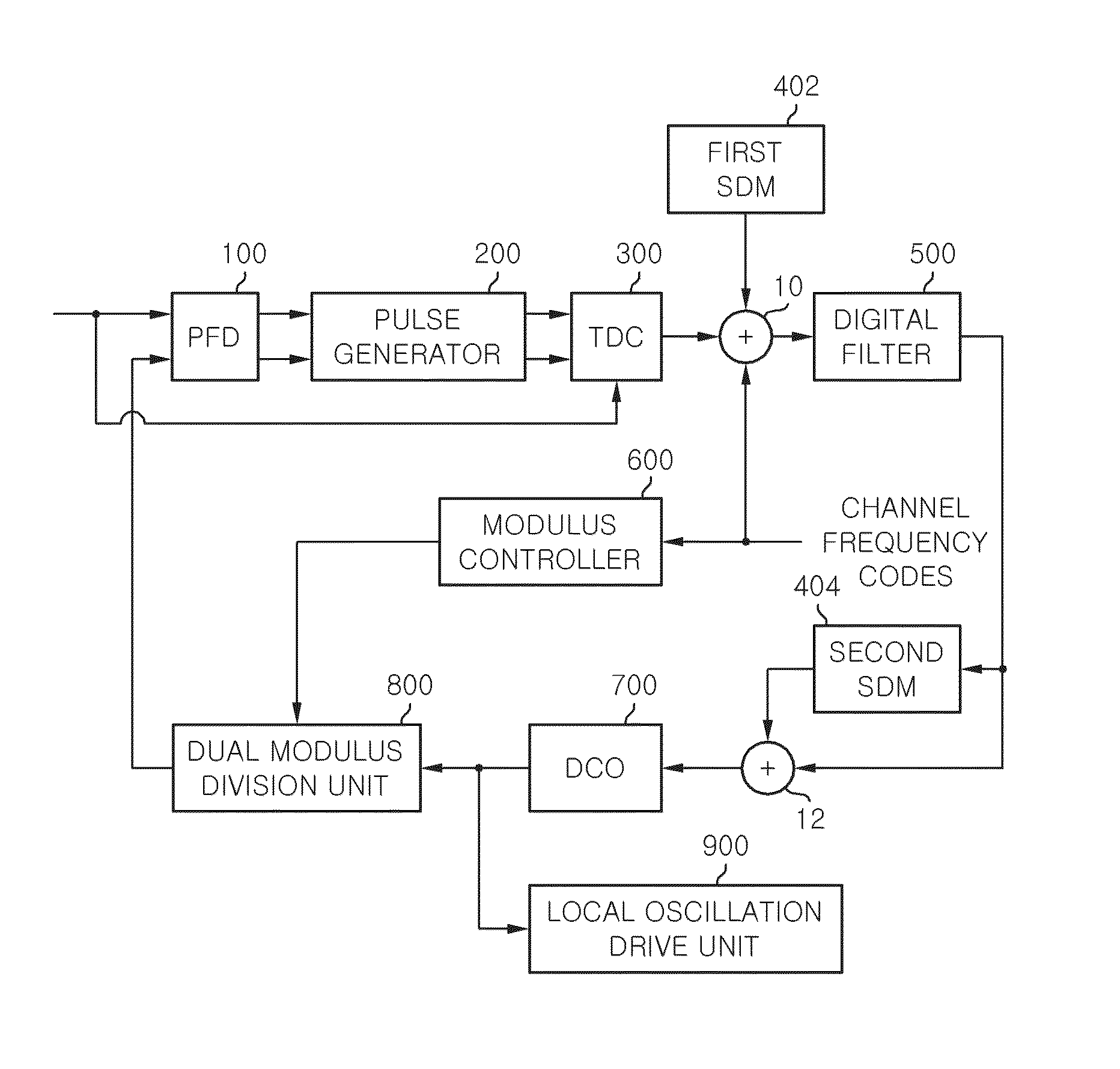
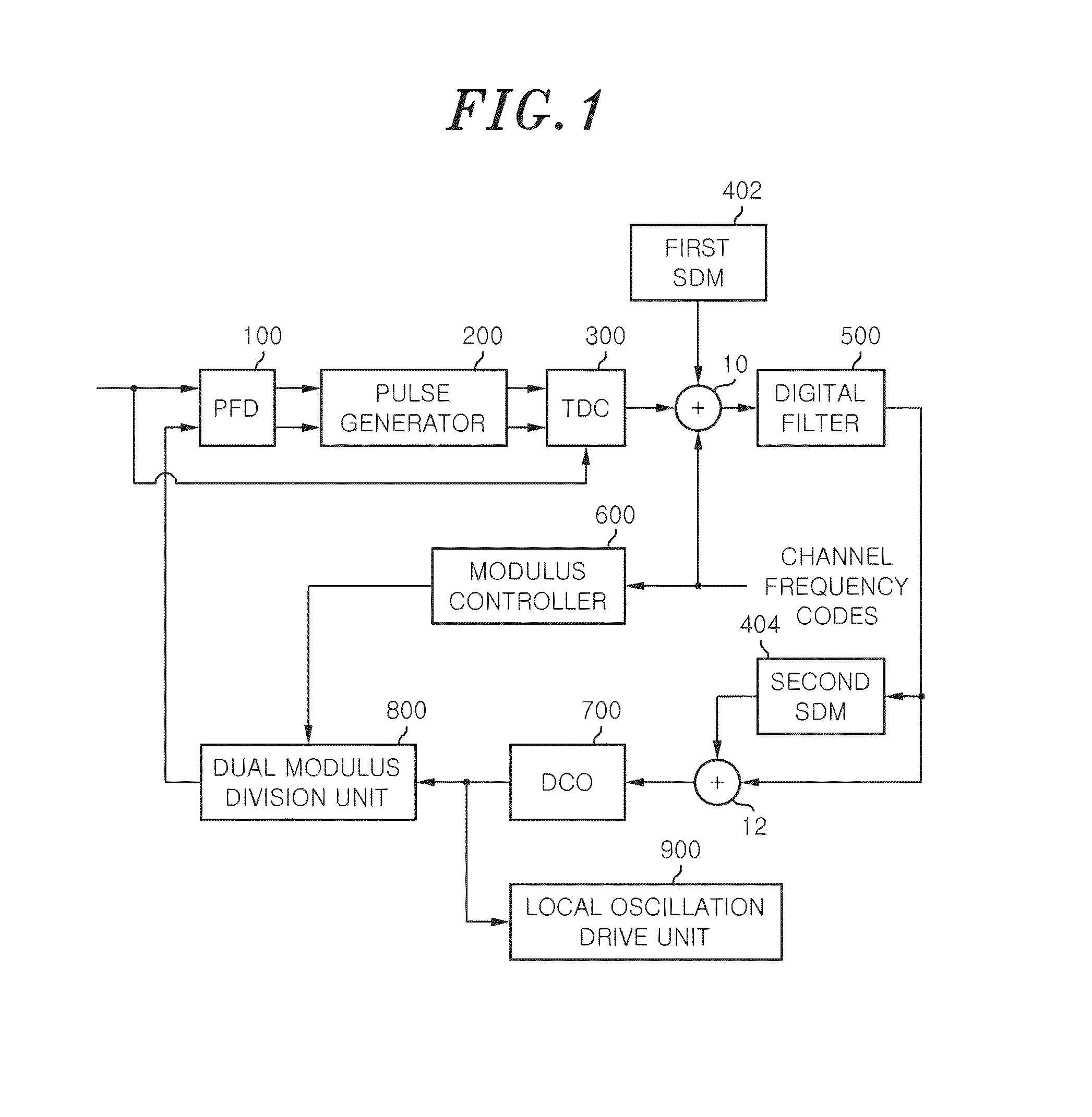
[0007]In view of the above, the present invention provides a digital phase-locked loop apparatus and a method of controlling the same, which are capable of easily enabling FSK using the digital phase-locked loop apparatus when a transmitter and a receiver are implemented using FSK in a wireless communication system.
[0008]Further, the present invention provides a digital phase-locked loop apparatus and a method of controlling the same, which are capable of flexibly varying the channel of an output frequency without an additional apparatus when the channel is varied.
[0009]Yet another object of the present invention is to provide a digital phase-locked loop apparatus and a method of controlling the same, which are capable of reducing time and costs by providing flexibility when a process used in a final circuit is varied or scaled down.
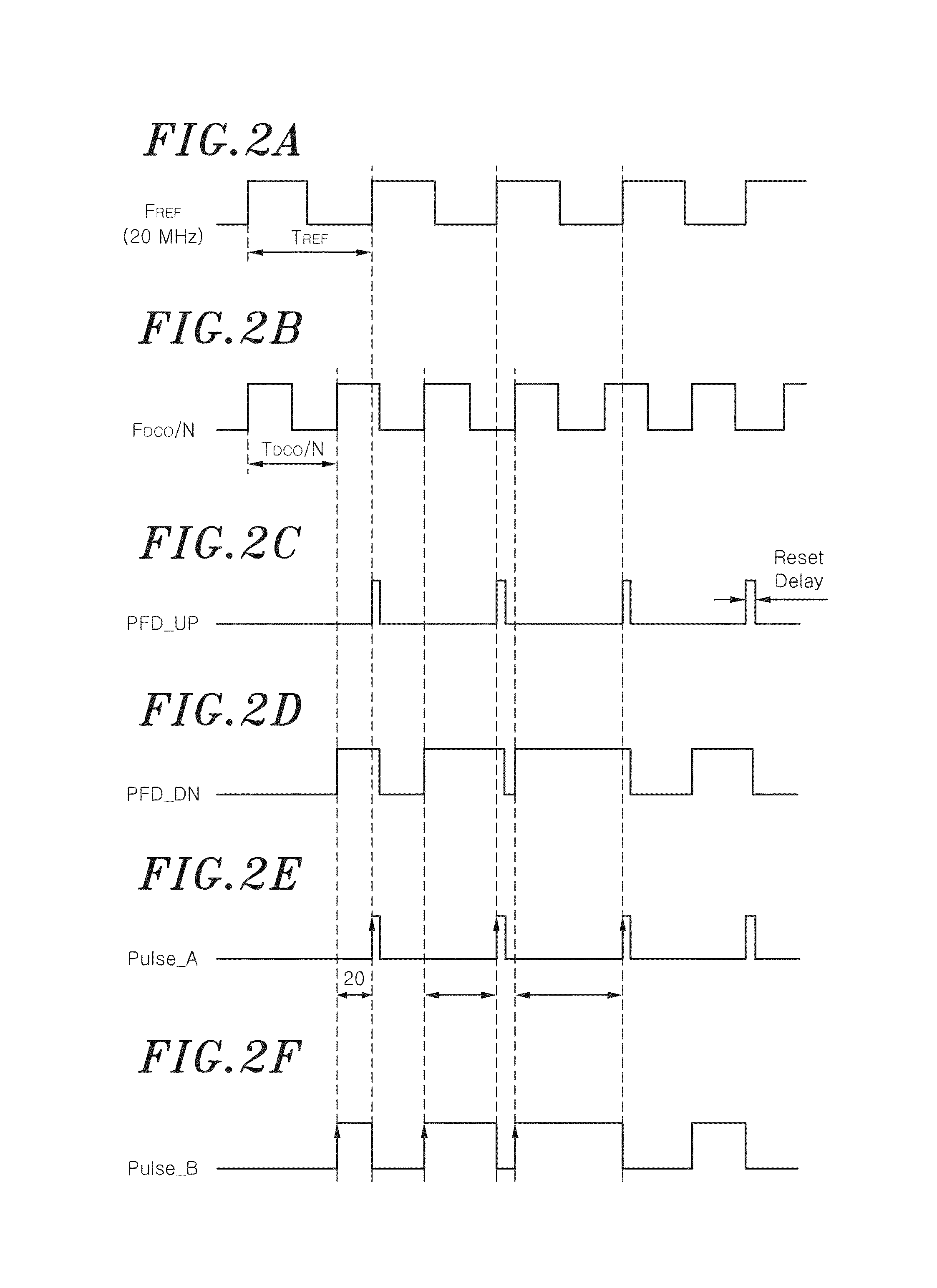
[0017]The pulse generator may remove the reset delay signal from the output value of the PFD by performing digital operation processing.

Problems solved by technology

The implementation of a transceiver capable of reducing power consumption in wireless communication and being flexibly used in many applications has become a recent issue.
This may become a cause of increased current consumption.
Furthermore, since almost all circuit blocks must be redesigned when a process is varied or scaled down because the analog phase-locked loop is very sensitive to a process, the time and cost are increased.
Furthermore, there is a limitation to a part that reduces in-band noise from among the phase noise of the analog phase-locked loop circuit.
In this case, a lot of current is consumed because the blocks must operate at a high speed.

Method used


Image

  • Digital phase-locked loop apparatus using frequency shift keying and method of controlling the same
  • Digital phase-locked loop apparatus using frequency shift keying and method of controlling the same
  • Digital phase-locked loop apparatus using frequency shift keying and method of controlling the same

Examples


Embodiment Construction

[0038]Embodiments of the present invention will be described herein, including the best mode known to the inventors for carrying out the invention. Variations of those embodiments may become apparent to those of ordinary skill in the art upon reading the foregoing description. The inventors expect skilled artisans to employ such variations as appropriate, and the inventors intend for the invention to be practiced otherwise than as specifically described herein. Accordingly, this invention includes all modifications and equivalents of the subject matter recited in the claims appended hereto as permitted by applicable law. Moreover, any combination of the above-described elements in all possible variations thereof is encompassed by the invention unless otherwise indicated herein or otherwise clearly contradicted by context.

[0039]In the following description of the present invention, if the detailed description of the already known structure and operation may confuse the subject matter...


PUM


Abstract

A digital phase-locked loop apparatus using FSK includes a PFD detecting phase differences between a reference clock and a frequency-divided signal, and a first adder for generating first digital control codes by adding first digital codes, second digital codes, and channel frequency codes including channel information to each other, the first digital codes being converted from time differences between first and second pulses. The apparatus further includes a digital filter correcting errors of the first digital control codes to generate second digital control codes, a DCO for varying an oscillating frequency in accordance with a digital tuning word based on the second digital control codes, and a dual modulus division unit dividing the oscillating frequency into a frequency-divided signal.

Description

RELATED APPLICATION(S)[0001]This application claims the benefit of Korean Patent Application No. 10-2011-0082672, filed on Aug. 19, 2011, which is hereby incorporated by references as if fully set forth herein.FIELD OF THE INVENTION[0002]The present invention relates to a phase-locked loop apparatus which operates using a digital method, rather than an existing analog method, so as to perform Frequency Shift Keying (FSK) at a transmitting stage and, more particularly, to a digital phase-locked loop apparatus using FSK and a method of controlling the same, which are capable of reducing additional circuits and flexibly selecting a channel by receiving the data of a transmitter as input to the digital phase-locked loop apparatus and then performing frequency shifting on the data.BACKGROUND OF THE INVENTION[0003]The implementation of a transceiver capable of reducing power consumption in wireless communication and being flexibly used in many applications has become a recent issue. To me...

Claims


Application Information

Patent Timeline
Patent Type & Authority Patents(United States)
IPC IPC(8): H03L7/06
CPCH03L7/0992H03L7/183H03L7/08H03M3/02
Inventor LEE, SEUNG SIKCHOI, SANGSUNGJEON, YOUNG AELEE, SANGJAEKIM, BYOUNG HAKOH, MI KYUNGSHIN, CHEOL-HOLEE, KANG-YOONPU, YOUNGGUNPARK, JOON-SUNG
Owner ELECTRONICS & TELECOMM RES INST
Why Eureka
Try Eureka