Steam generator

a technology of steam generator and steam pump, which is applied in the direction of steam boiler components, heating types, washing apparatus, etc., can solve the problems of inability to clean and disinfect, limited size of conventional steam generator, wet steam, etc., and achieves simple structure, prolonging the time that water passes through the heating unit, and increasing the contact area. effect of water conta

Inactive Publication Date: 2013-10-08
ZWEITA INT
View PDF10 Cites 29 Cited by
  • Summary
  • Abstract
  • Description
  • Claims
  • Application Information

AI Technical Summary

Benefits of technology

[0006]The primary object of the present invention is to provide a steam generator, which comprises a housing, a heating unit, an electrothermal unit and a one-way valve. In particular, the heating unit includes a first spiral channel and a second spiral channel to extend the time that the water passes through the heating unit and to increase the contact area of the water contact with the heating unit, such that the water can be heated and vaporized totally to generate steam.
[0007]A further object of the present invention is to provide a steam generator, which provides the one-way valve coupled to the water inlet. The one-way valve is pushed to temporarily stop the water form entering for the water to be totally vaporized to generate steam, and then the steam sprays out. After the steam is sprayed out, the inside pressure will lower and the one-way valve will be pushed away to open the water outlet again. The water automatically enters the steam generator through the water inlet. The steam generator of the present invention is simple in structure and cost-effective, providing an automatic water supply and re-heating function.

Problems solved by technology

The size of a conventional steam generator is limited and the steam can't keep the outlet at a high temperature, resulting in wet steam.
This cannot clean and disinfect and causes a second pollution due to the wet steam having moisture.
Sometimes, this may damage furniture.
A high temperature and moist environment will cause bacteria.
This makes the steam generator complicated and increases the cost.
Furthermore, it is not easy to adjust and maintain the steam generator.

Method used


Image

  • Steam generator
  • Steam generator
  • Steam generator

Examples


Embodiment Construction

[0019]Embodiments of the present invention will now be described, by way of example only, with reference to the accompanying drawings.

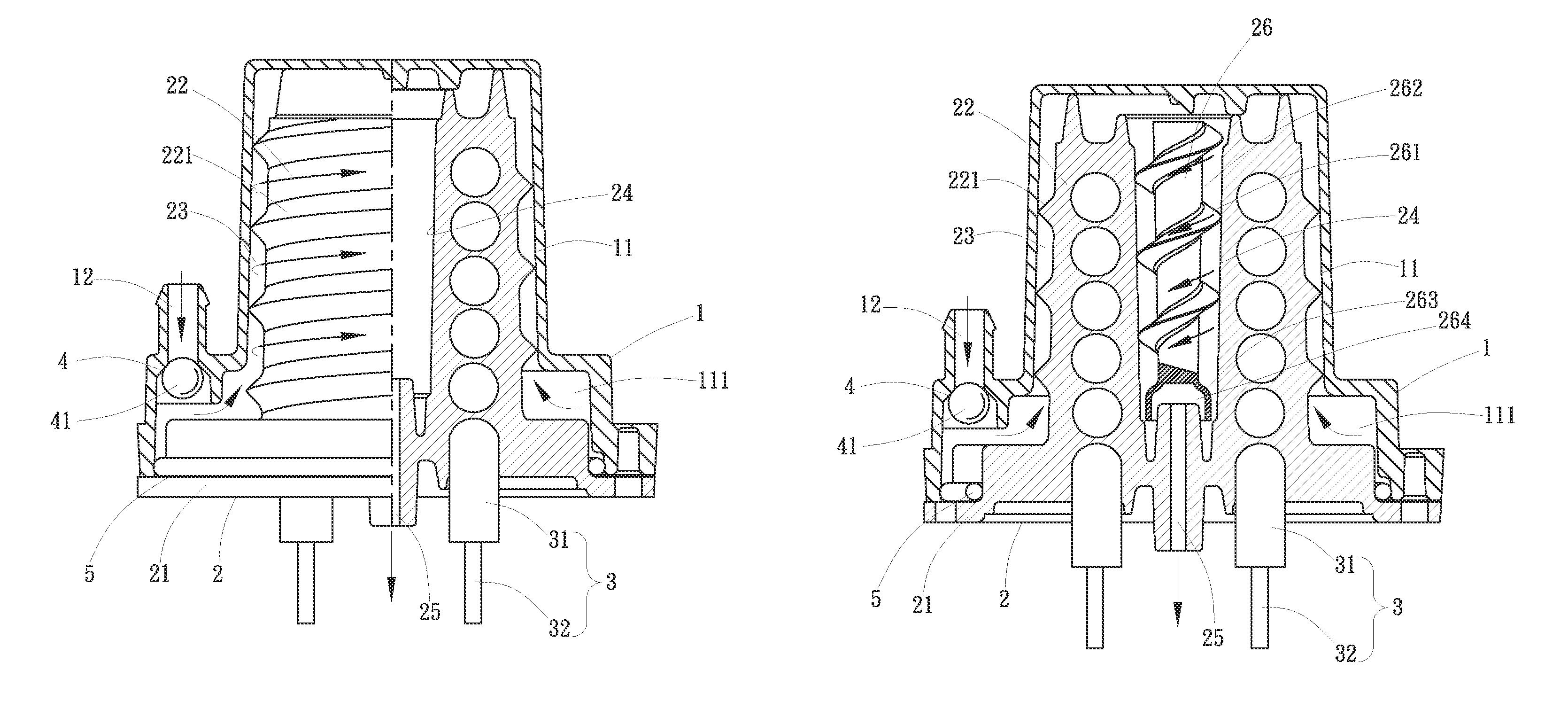
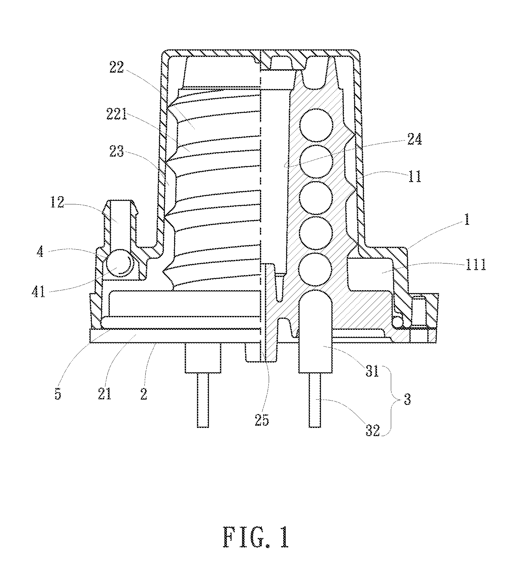
[0020]As show in FIG. 1 to FIG. 3, the steam generator according to a preferred embodiment of the present invention comprises a housing 1, a heating unit 2, an electrothermal unit 3 and a one-way valve 4.

[0021]The housing 1 is a cylindrical or other shape configuration. The housing 1 comprises a chamber 11 at one end and a water inlet 12 at one side of the housing 1. The water inlet 12 communicates with the chamber 11.

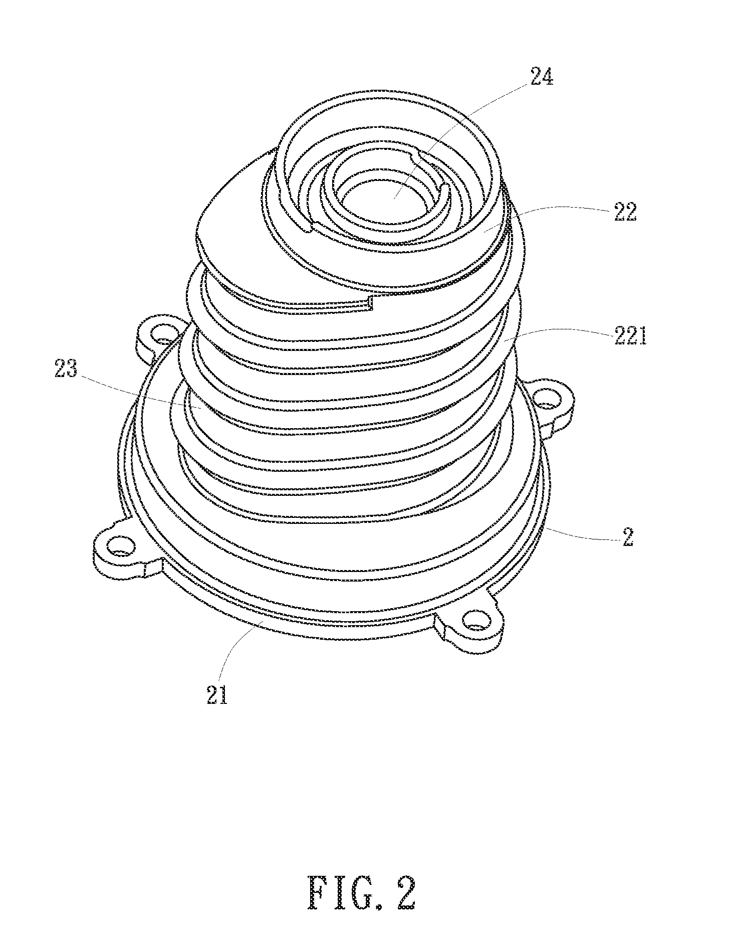
[0022]The heating unit 2 is made of a heat conduction metallic material. The heating unit 2 comprises an end cap 21 and a cylindrical heating portion 22. The end cap 21 is to seal an open end of the chamber 11 of the housing 1. The heating portion 22 is located in the chamber 11. The heating portion 22 has a first spiral ring 221 formed on an outer wall of the heating portion 22. An outer circumferential portion of the first spiral ring ...


PUM


Abstract

A steam generator includes a housing, a heating unit, an electrothermal unit and a one-way valve. The housing has a chamber and a water inlet. The heating unit includes a heating portion extending into the chamber. The heating portion has a first spiral channel thereon. One end of the heating portion is formed with a vaporization room and a steam outlet. The vaporization room has a second spiral channel therein to extend the time that the water and the wet steam pass through the heating unit so as to provide a complete heating and vaporizing function. Besides, by the one-way valve coupled to the water inlet, the steam generator of the present invention is simple in structure and cost-effective, providing an automatic water supply and re-heating function.

Description

BACKGROUND OF THE INVENTION[0001](a) Field of the Invention[0002]The present invention relates to a steam generator, and more particularly to a steam generator applied to an electric appliance which needs to spray steam. The steam generator is capable of totally vaporizing water to generate steam.[0003](b) Description of the Prior Art[0004]A steam generator is widely used to an electric appliance, such as a steam cleaning spray gun, a steam electric iron, a steam vacuum cleaner, a steam wiper, a steam stirrer, a steam cleaning machine and so on. The size of a conventional steam generator is limited and the steam can't keep the outlet at a high temperature, resulting in wet steam. This cannot clean and disinfect and causes a second pollution due to the wet steam having moisture. Sometimes, this may damage furniture. A high temperature and moist environment will cause bacteria.[0005]Besides, the conventional steam generator is provided with many control members at the water inlet to p...

Claims


Application Information

Patent Timeline
Patent Type & Authority Patents(United States)
IPC IPC(8): D06F75/18F22B1/28F22B37/60
CPCF22B1/28
Inventor HSU, CHIH-KAO
Owner ZWEITA INT
Why Eureka
Try Eureka