Secondary user interface

a technology of user interface and display screen, applied in computing, instruments, electric digital data processing, etc., can solve the problems of requiring a significant amount of time relative to the presentation of scanned lines of data, modern monitors have become much faster in their retrace speed, and a significant amount of time when the electron gun cannot be blanked, so as to increase the accessible area of the display. , the effect of fast retrace speed

Inactive Publication Date: 2013-10-08
OSTENDO TECH INC
View PDF10 Cites 1 Cited by
  • Summary
  • Abstract
  • Description
  • Claims
  • Application Information

AI Technical Summary

Benefits of technology

[0010]When the electron gun in a CRT retraces to the left of the screen or the top of the screen, it requires a significant amount of time relative to the presentation of a scanned line of data. During the retrace, the electron gun is turned off (“blanked”). If the blanking time required for the retrace is equal to the amount of time available, there is no usable overscan. However, modern monitors have become much faster in their retrace speeds, leaving a significant amount of time when the electron gun need not be blanked, allowing a displayable border. In the prior art, although the border is usually “black” (the gun is turned off), it is well known to specify that the border shall be given any one of six colors. Standard BIOS allows a specification of this color. The desired color is simply specified in one of the registers for the video controller. No data for this color is stored in the buffer of video memory for the display. This invention establishes an additional video buffer for the border and allows this buffer to be written with display data like the regular display buffer. The display area is thereby expanded, on one or more edges, to provide a visible area previously invisible. The pixels within this newly visible area of the display are made accessible to programs through an application programming interface (API) component of this invention. A program incorporating a graphical user interface may be displayed in the previously blanked area of the display, functionally increasing the accessible area of the display without hardware modification.

Problems solved by technology

When the electron gun in a CRT retraces to the left of the screen or the top of the screen, it requires a significant amount of time relative to the presentation of a scanned line of data.
However, modern monitors have become much faster in their retrace speeds, leaving a significant amount of time when the electron gun need not be blanked, allowing a displayable border.

Method used


Image

  • Secondary user interface
  • Secondary user interface
  • Secondary user interface

Examples


Embodiment Construction

[0027]The present invention includes techniques for providing and using a secondary or additional user interface, preferably a secondary graphical user interface or secondary GUI, to be present on the display at least apparently simultaneously with the primary user interface, such as the conventional desktop.

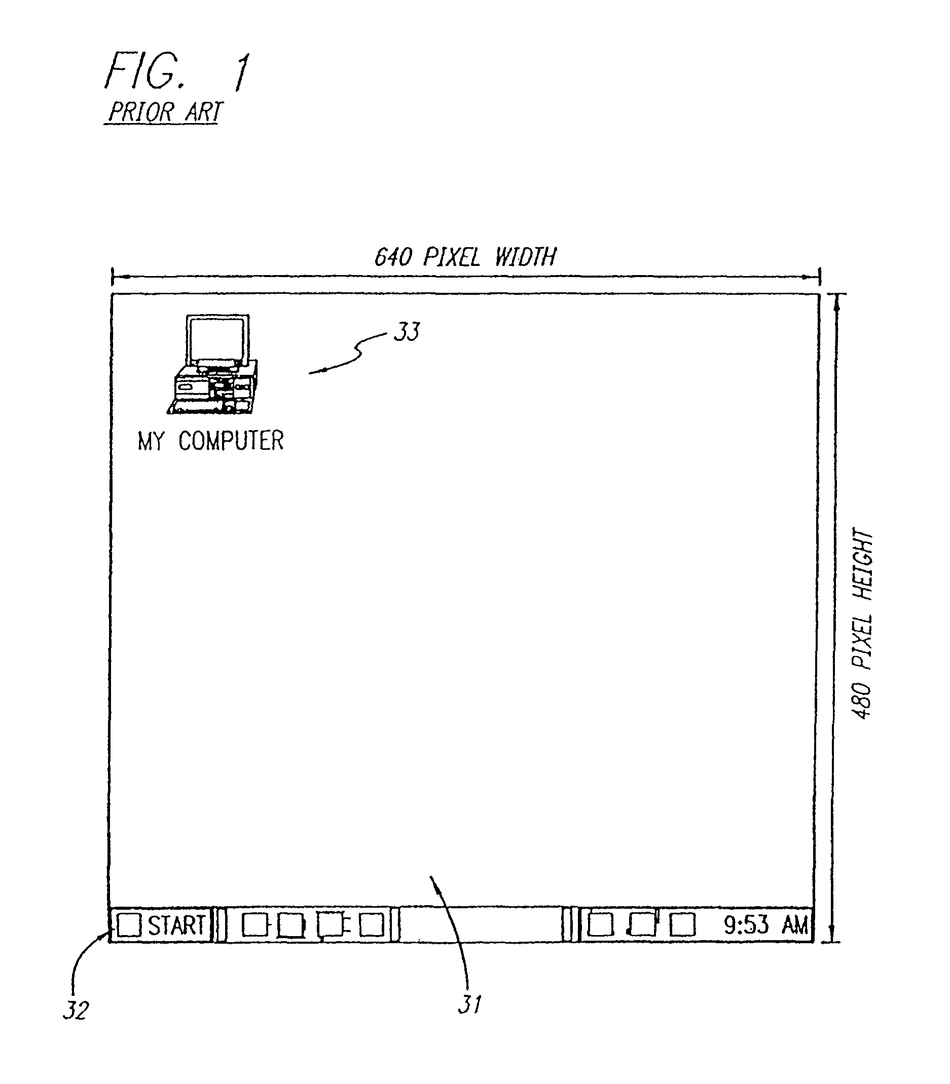
[0028]In a preferred embodiment, programming mechanisms and interfaces in a computer system provide the secondary GUI in a convenient and currently unused potential display area by providing access and visibility to a portion of the monitor display normally ignored and inaccessible (hereinafter “overscan area”). FIG. 1 shows a standard prior art display desktop running Microsoft Windows 95™. Within the desktop 31 are the taskbar 32 and desktop icons 33.

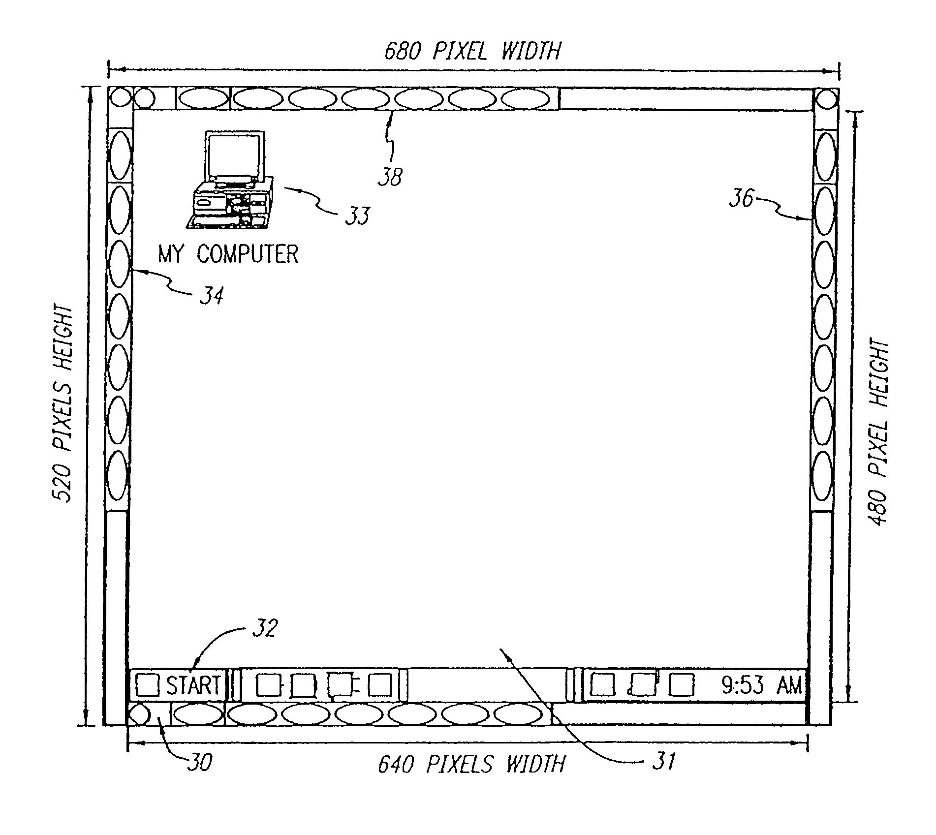
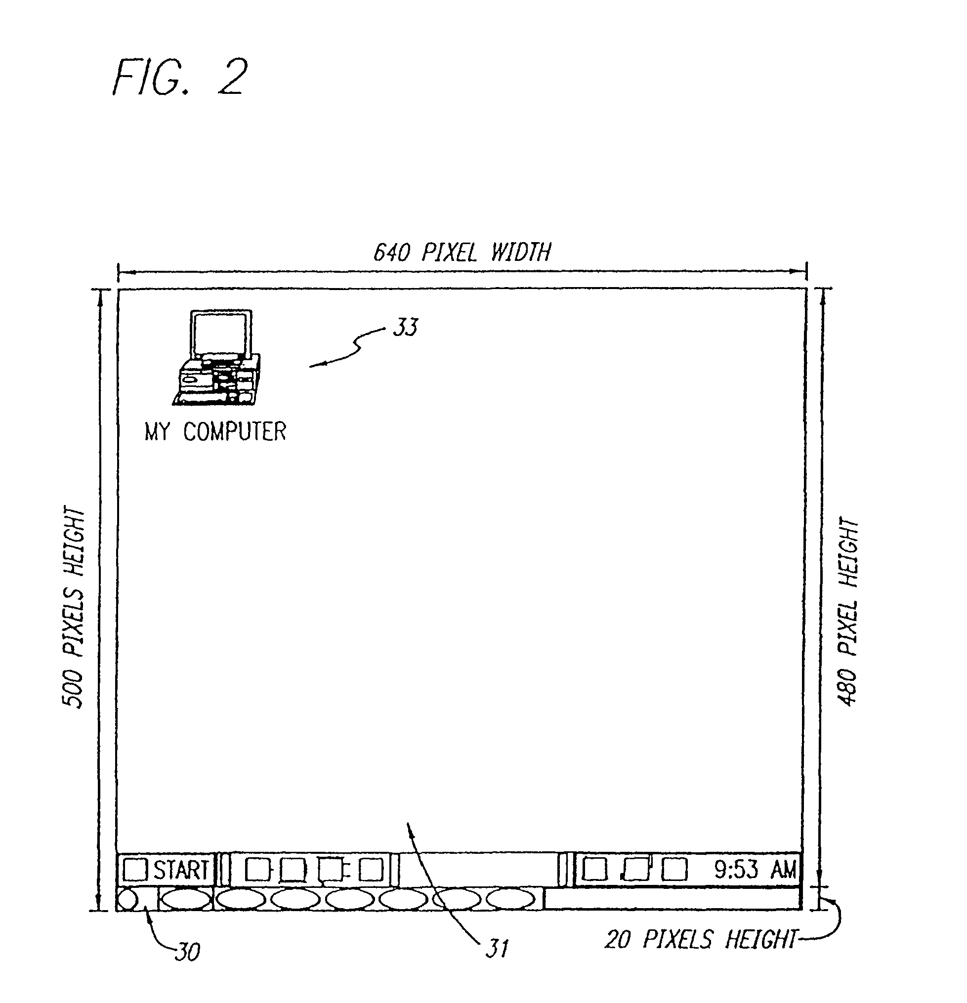
[0029]In a preferred embodiment of the present invention, a graphical user interface image is painted onto one or more of the sides of the overscan area as shown in FIGS. 2 and 3. FIGS. 2 and 3 show depictions of a Super VGA (SVGA...


PUM


Abstract

A method for creating and accessing a graphical user interface in the overscan area outside the area of the display normally utilized by the common operating systems. This normal display area is generally known as the “desktop”. The desktop serves as a graphical user interface to the operating system. The desktop displays images representing files, documents and applications available to the user. The desktop is restricted in the common environments to a predetermined set of resolutions (e.g., 640×480, 800×600, 1024×768) as defined by VGA and SVGA standards. Displayable borders outside this area are the overscan area.

Description

CROSS-REFERENCE TO RELATED APPLICATIONS[0001]This application is a continuation of U.S. application Ser. No. 10 / 971,503 filed Oct. 21, 2004; which is a Continuation of U.S. application Ser. No. 09 / 960,850 filed Sep. 21, 2001, now issued as U.S. Pat. No. 6,828,991; which is a continuation of U.S. application Ser. No. 09 / 191,322 filed Nov. 13, 1998, now issued as U.S. Pat. No. 6,330,010 on Dec. 11, 2001; which claims priority to Provisional Application No. 60 / 093,217 filed Jul. 17, 1998.BACKGROUND OF THE INVENTION[0002]1. Field of the Invention[0003]This invention relates to computer user interface displays and in particular, the use of a user interface separate from the standard user interface display.[0004]2. Description of the Prior Art[0005]There was a time when the most popular operating system for personal computers (DOS) did not include a graphical user interface. Any company could create a “menu” or “shell” which would be the first program launched upon starting the computer a...

Claims


Application Information

Patent Timeline
Patent Type & Authority Patents(United States)
IPC IPC(8): G06F3/048G09G5/02G09G5/00
CPCG06F3/033G06F9/44G09G3/3611G09G2310/061G09G2360/02
Inventor NASON, D. DAVIDO'ROURKE, THOMAS C.CAMPBELL, J. SCOTT
Owner OSTENDO TECH INC
Why Eureka
Try Eureka