Hydraulic shock absorber

a technology of hydraulic shock absorber and vehicle height adjustment, which is applied in the direction of shock absorbers, mechanical devices, transportation and packaging, etc., can solve the problems of hydraulic fluid contamination, deformation of hydraulic fluid, and affecting the performance of hydraulic shock absorbers, so as to reduce the number of components and increase space efficiency , the effect of avoiding hydraulic fluid contamination

Active Publication Date: 2013-10-15
HITACHI ASTEMO LTD
View PDF13 Cites 59 Cited by
  • Summary
  • Abstract
  • Description
  • Claims
  • Application Information

AI Technical Summary

Benefits of technology

[0006]The present invention has been made in view of the above-described circumstances. An object of the present invention is to provide a self-leveling hydraulic shock absorber capable of increasing the space efficiency to ensure the necessary capacities of the reservoir and the hydraulic fluid tank while reducing the number of component parts and also capable of avoiding contamination of the hydraulic fluid and thermal deformation, which might otherwise be caused by welding.

Problems solved by technology

However, vehicles having relatively large carrying capacities, e.g. vans and wagons, may be degraded in ride quality and steering stability by a large change in vehicle height due to a change in the carrying load resulting from the occupant getting on or off the vehicle, baggage loading or unloading, and so forth.
Further, if the rear wheel-side vehicle height is lowered (rear sagging) by the load carried on the vehicle, the optical axis of the headlight is undesirably directed upward.
Therefore, sputtering occurring during welding may cause contamination of the hydraulic fluid.
In addition, heat of welding may deform the annular members, resulting in degradation of sealing performance.

Method used


Image

  • Hydraulic shock absorber
  • Hydraulic shock absorber
  • Hydraulic shock absorber

Examples


Embodiment Construction

[0013]An embodiment of the present invention will be explained below in detail with reference to the accompanying drawings.

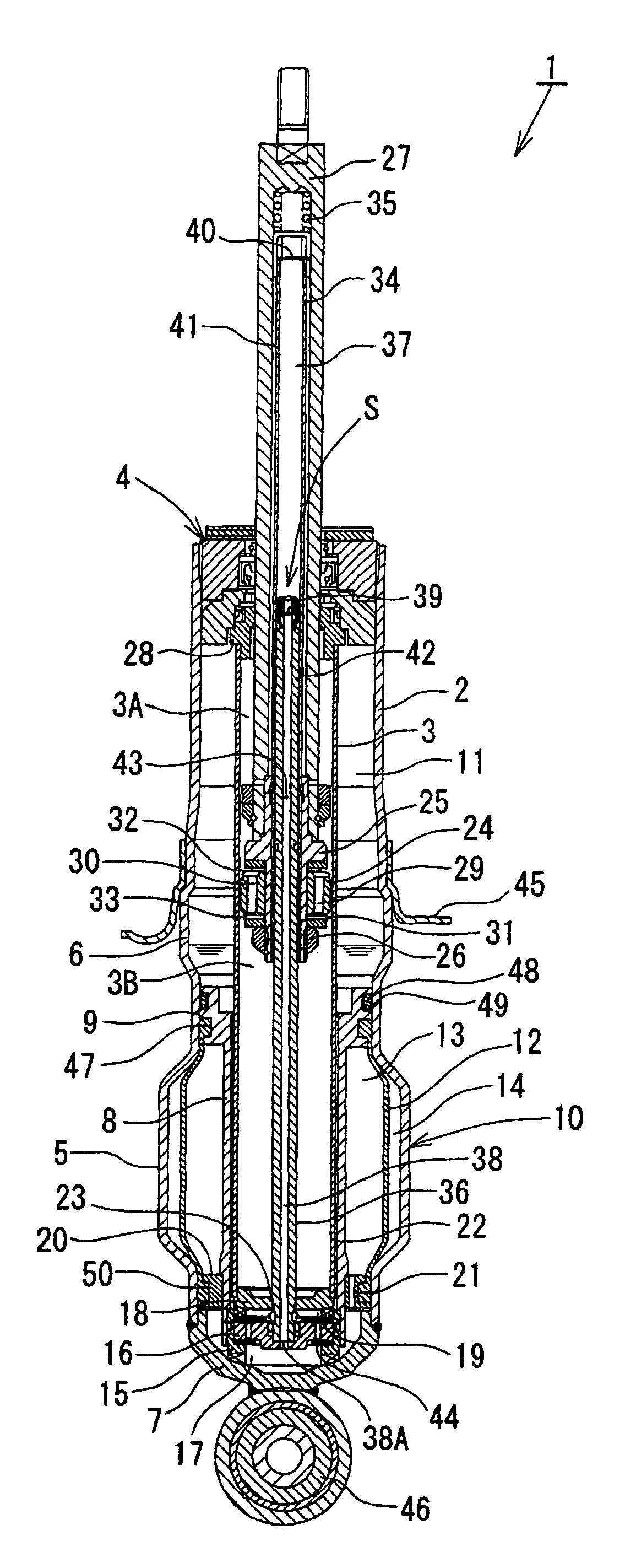
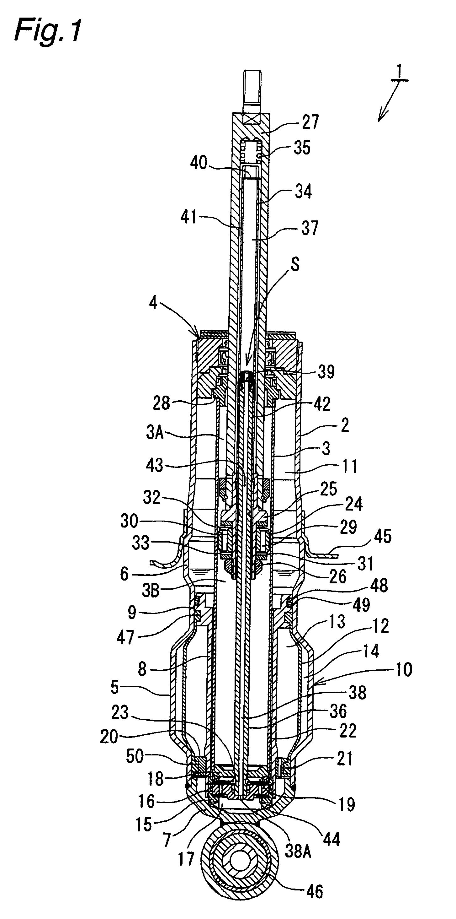
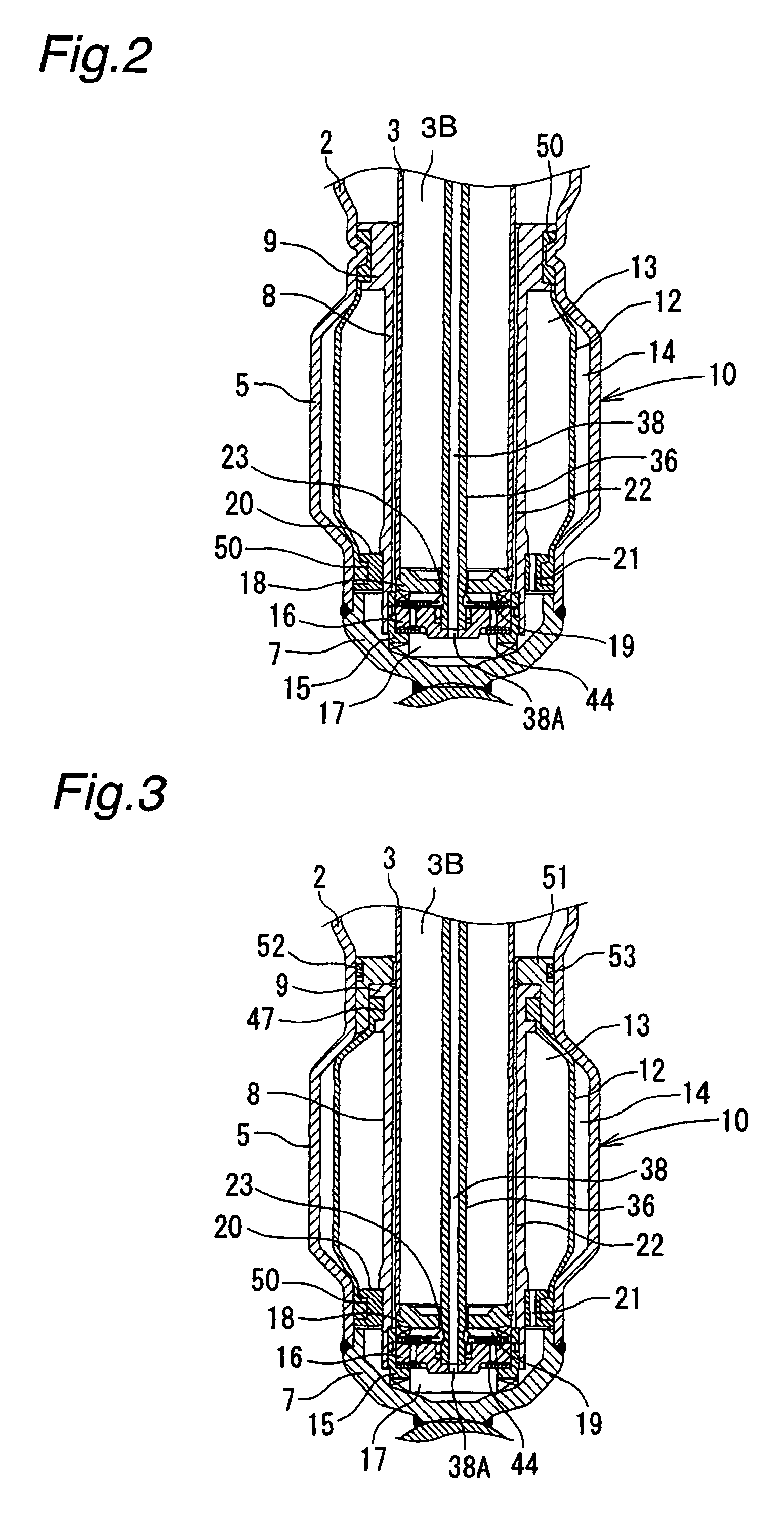
[0014]As shown in FIG. 1, a hydraulic shock absorber 1 has a dual tube structure in which a cylinder 3 is inserted in a cylindrical casing 2 (outer tube), one end of which is substantially closed. A seal member 4 is fitted in the opening of the casing 2, thereby forming an annular chamber between the casing 2 and the cylinder 3. The lower end of the casing 2 is bulged radially outward by bulging process or the like to form a bulged portion 5. A portion of the casing 2 above the bulged portion 5 is slightly enlarged in diameter to form a spring retainer support portion 6. The bottom of the casing 2 is closed with a cap member 7 welded thereto. A partition member 8 is inserted between the bulged portion 5 of the casing 2 and the cylinder 3. The partition member 8 has an outer flange portion 9 at the upper end thereof. The outer flange portion 9 is fitted to the ca...


PUM


Abstract

A piston connected with a piston rod is fitted in a cylinder having a hydraulic fluid sealed therein. A damping force is generated through extension and compression disk valves and an orifice. Vehicle height adjustment is performed with a self-leveling mechanism by transferring the hydraulic fluid between the cylinder and a hydraulic fluid tank. A bladder of the hydraulic fluid tank is clamped between an outer flange portion of a partition member and a casing. Because the hydraulic fluid tank is formed without welding, it is possible to avoid contamination of the hydraulic fluid by welding sputter and thermal deformation. Provision of an O-ring on the outer flange portion can reduce the pressure acting from a reservoir on the clamped portion of the bladder and hence prevent dislodging of the bladder.

Description

BACKGROUND OF THE INVENTION[0001]The present invention relates to a hydraulic shock absorber with an automatic vehicle height adjusting mechanism that is installed in a suspension system of a vehicle such as an automobile.[0002]In general, vehicles such as automobiles have a hydraulic shock absorber installed between sprung and unsprung members of a suspension system to damp vibrations of the sprung and unsprung members, thereby improving ride quality and steering stability. However, vehicles having relatively large carrying capacities, e.g. vans and wagons, may be degraded in ride quality and steering stability by a large change in vehicle height due to a change in the carrying load resulting from the occupant getting on or off the vehicle, baggage loading or unloading, and so forth. Further, if the rear wheel-side vehicle height is lowered (rear sagging) by the load carried on the vehicle, the optical axis of the headlight is undesirably directed upward. Accordingly, there has bee...

Claims


Application Information

Patent Timeline
Patent Type & Authority Patents(United States)
IPC IPC(8): F16F9/14
CPCB60G17/08F16F9/092B60G2202/24F16F9/10F16F9/32
Inventor MAEDA, ATSUSHINAKAGAWA, REIJI
Owner HITACHI ASTEMO LTD
Why Eureka
Try Eureka