
System for cardiac arrhythmia detection

a technology of cardiac arrhythmia and detection system, which is applied in the field of system for heart performance characterization and abnormality detection, can solve the problems of false alarm, failure to efficiently interpret and characterize cardiac signals during pacing, and use of p wave analysis methods, so as to improve the analysis and interpretation of cardiac electrophysiological activities.

Active Publication Date: 2013-10-15
PIXART IMAGING INC
View PDF27 Cites 3 Cited by
  • Summary
  • Abstract
  • Description
  • Claims
  • Application Information

AI Technical Summary

Benefits of technology

The patent describes a system that can better analyze and understand the electrical activity of the heart by measuring the signals that occur during heart beats. The system uses a pace signal to synchronize the data and calculates time intervals between heart beats. These intervals are then compared to a threshold value and an alert message is generated if the threshold is exceeded. The technical effect of this system is the improved ability to analyze and interpret cardiac electrophysiological activities, which can help with the detection and diagnosis of heart abnormalities.

Problems solved by technology

Known systems using P wave analysis methods, for example, typically fail to efficiently interpret and characterize cardiac signals during pacing.
Furthermore, noise and artifact effects during pacing may be higher which may distort a cardiac electrophysiological signal, resulting in a false positive alarm, especially in ICD (implantable cardioverter-defibrillator) patients.
However RR wave detection may not be accurate during pacing or during electrical stimulation, especially for excitation time tracking and detection of signal morphology variation.
Additionally unsuccessful pacing heart beats may cause variation (as well as unnecessary alarms or warnings) in signal evaluation and calculation.
Furthermore, there may be substantial heart electrophysiological characteristic changes: such as absence of a P wave in the pacing signals and detection of an ST segment exceeding a 0.1 mV threshold (as typically used for cardiac condition detection) may not work for ischemia detection in pacing (especially for intra-cardiac electrograms (ICEG)).
Also substantial signal magnitude shift, distortion or variation may occur in the presence of pacing.
Known methods based on RR wave detection may indicate unnecessary time variation for cardiac signal morphology analysis and therefore may be inaccurate in cardiac function evaluation and pathology diagnosis and known methods based on detecting amplitude (voltage) changes and variation may not be accurate for cardiac function evaluation and pathology diagnosis.
Known pacing cardiac signals analysis is typically subjective and needs extensive physician pacing analysis experience and may be not be able to qualitatively and quantitatively capture or characterize signal changes, and predict a pathological trend, especially a real time growing trend of a cardiac arrhythmia, such as a pathology trend from low risk to medium, and then to high risk (severe and fatal) rhythm (especially in VT growing arrhythmia, for example).
Known excitation analysis typically involves tune stamping an R wave transition along myocardial tissue (such as by using different leads in a catheter coupled to different portions of cardiac tissue) but lack accurate methods to measure time duration and variation of signals from individual cardiac tissue portions.
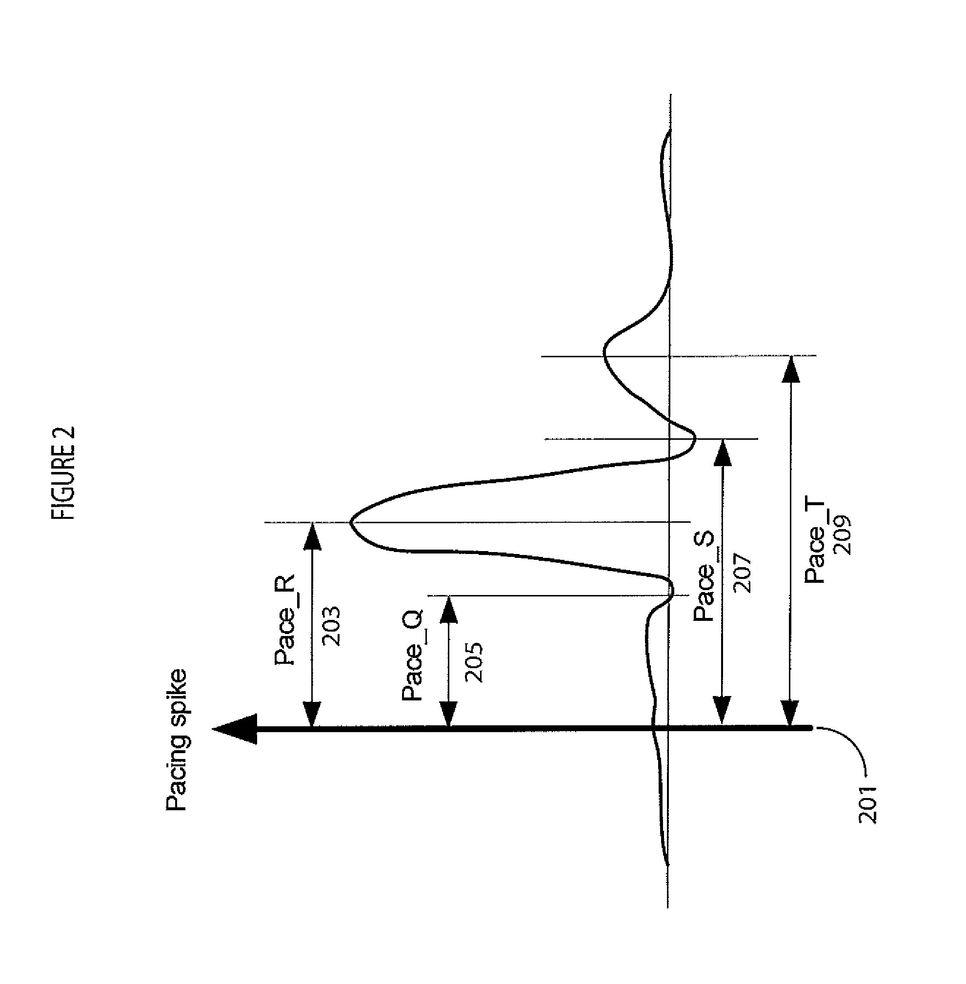
Absolute time synchronization variation may be used to detect local malfunctioning cardiac tissue, such as from a pacing spike to R wave, pacing spike to Q or S wave, but this may not work when patient pacing occurs.
In known clinical applications, pacing energy and rate determination are typically physician controlled based on experience and therefore prone to human error.

Method used


Image

  • System for cardiac arrhythmia detection
  • System for cardiac arrhythmia detection
  • System for cardiac arrhythmia detection

Examples


Embodiment Construction

[0015]A system improves accuracy and reliability of analysis and interpretation of cardiac electrophysiological activities, by characterizing cardiac electrophysiological signals (including surface ECG signals and intra-cardiac electrograms) in response to synchronization with a cardiac signal (such as for pacing or stimulation). The system synchronizes to locate and determine statistical characteristics and variation of different portions of a cardiac signal to provide an accurate time, location and severity of cardiac pathology and events for improved diagnosis. The system identifies cardiac disorders, differentiates cardiac arrhythmias, characterizes pathological severity, predicts life-threatening events, and supports evaluating drug delivery effects. The system analyzes cardiac electrophysiological signals and determines patient health status during pacing using pacing signal synchronization and stimulator control and adjustment (such as anti-tachycardia pacing) to provide an o...


PUM


Abstract

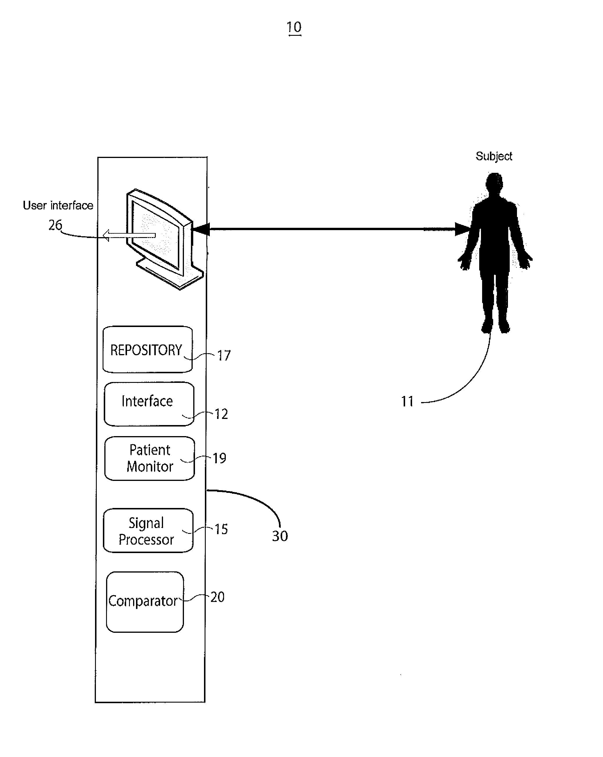
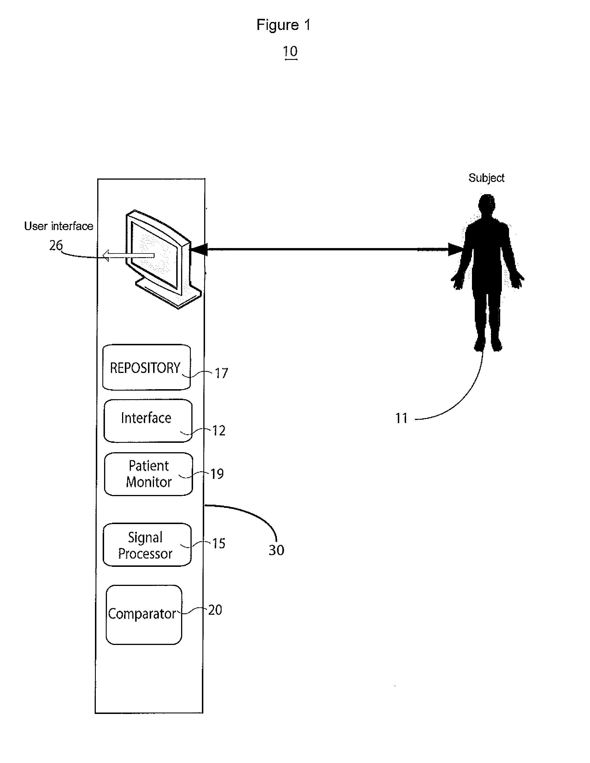
A system for heart performance characterization and abnormality detection includes an interface for receiving sampled data representing an electrical signal indicating electrical activity of a patient heart over multiple heart beat cycles and for receiving a pace signal indicating occurrence of a heart pace pulse applied to the heart. A signal processor uses the received sampled data and pace signal in calculating, a first signal characteristic value comprising a time interval between occurrence of the pace pulse and a cardiac cycle characteristic and a second signal characteristic comprising an average of the time intervals determined over a multiple heart cycles. A comparator compares at least one of the first and second characteristic values with a threshold value to provide a comparison indicator. A patient monitor generates an alert message associated with the threshold in response to the comparison indicator indicating a calculated signal characteristic value exceeds the threshold value.

Description

[0001]This is a non-provisional application of provisional application Ser. No. 61 / 292,285 filed 5 Jan. 2010, by H. Zhang.FIELD OF THE INVENTION[0002]This invention concerns a system for heart performance characterization and abnormality detection by determining characteristics of an electrical signal indicating electrical activity of a patient heart over multiple heart beat cycles and a pace signal indicating occurrence of a heart pace pulse applied to the heart.BACKGROUND OF THE INVENTION[0003]Cardiac pacing is used for clinical treatment and therapy of a patient and involves electrical cardiac stimulation to treat a tachyarrhythmia or bradyarrythmia. The pacing re-establishes circulatory integrity and normal hemodynamics that are compromised by a slow or fast heart rate by restoring an appropriate heart rate. Cardiac pacing may be lifesaving. Cardiac response signal analyses based on electrophysiological activity (such as surface ECG signals and ICEG (intra-cardiac electrograms))...

Claims


Application Information

Patent Timeline
Patent Type & Authority Patents(United States)
IPC IPC(8): A61N1/37
CPCA61N1/3702A61N1/37258A61N1/3621A61N1/3624A61N1/36557G16H40/63
Inventor ZHANG, HONGXUAN
Owner PIXART IMAGING INC
Learn More