
Damping device for hinge assembly

a technology of a damping device and a hinge assembly, which is applied in the direction of wing openers, door/window fittings, constructions, etc., can solve the problem of not having a damping function, and achieve the effect of convenient and convenient selection of turning on or turning

Active Publication Date: 2013-10-22
KING SLIDE WORKS CO LTD +1
View PDF37 Cites 56 Cited by
  • Summary
  • Abstract
  • Description
  • Claims
  • Application Information

AI Technical Summary

Benefits of technology

The invention allows the user to easily turn on or off the hinge assembly's damping function. This provides a convenient and easy way to control the damping device.

Problems solved by technology

When the housing is closed relative to the arm, the piston rod of the damper cannot contact the protruded portion of the adjustment member, and no damping function is available.

Method used


Image

  • Damping device for hinge assembly
  • Damping device for hinge assembly
  • Damping device for hinge assembly

Examples


Embodiment Construction

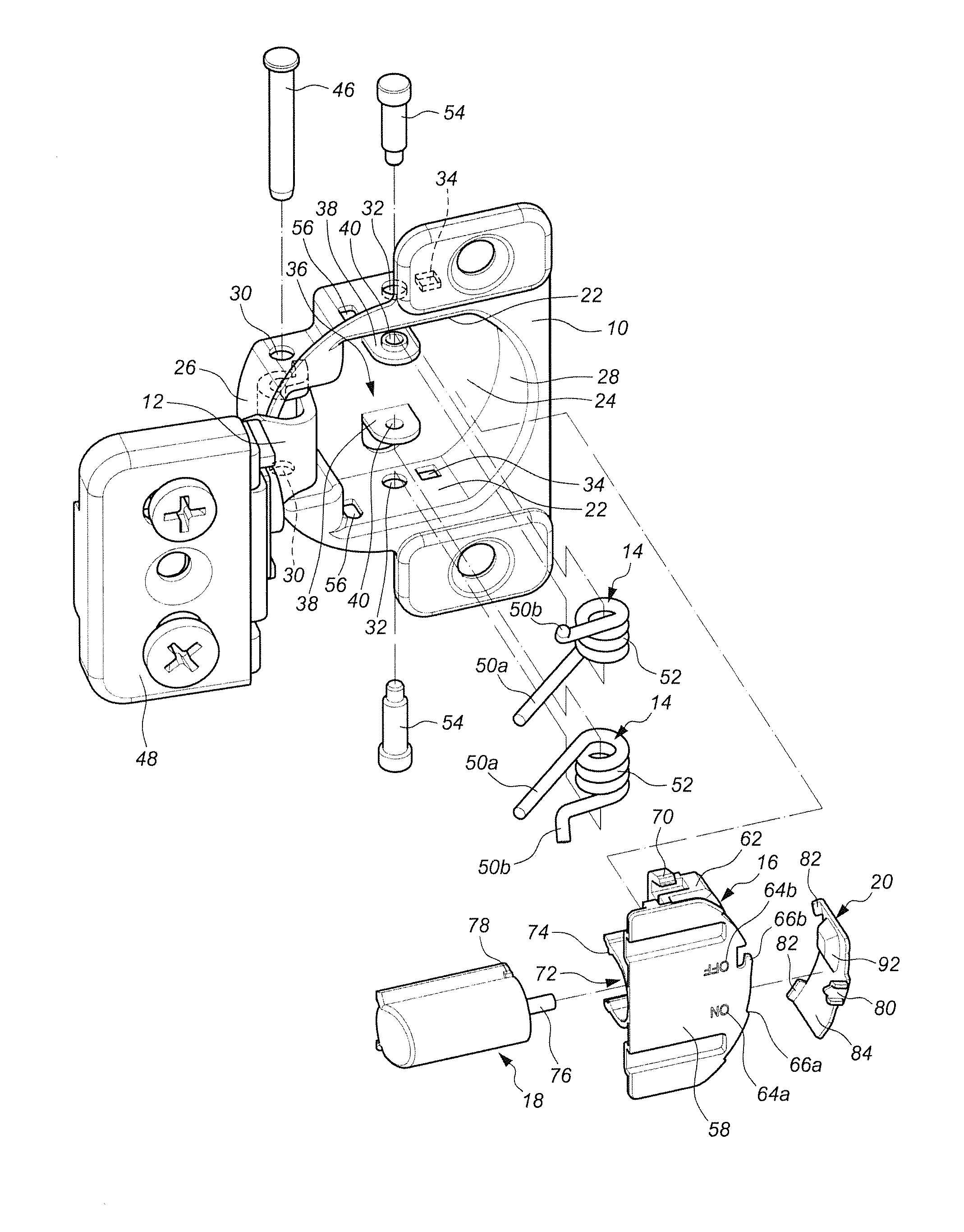
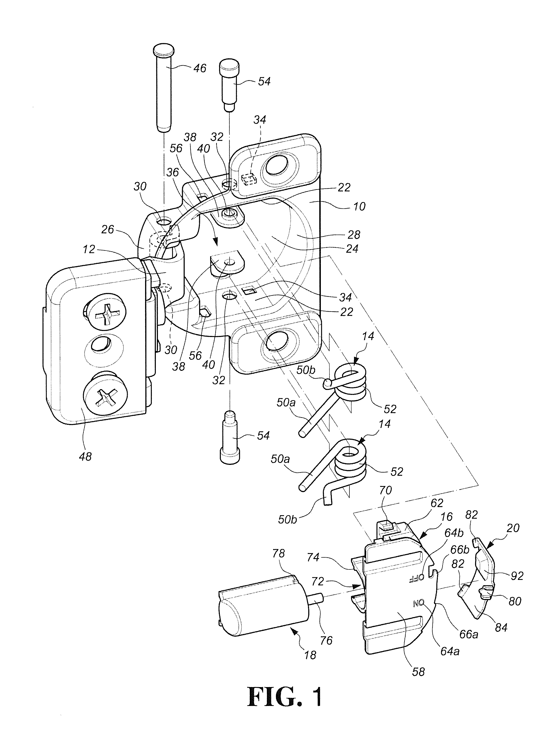
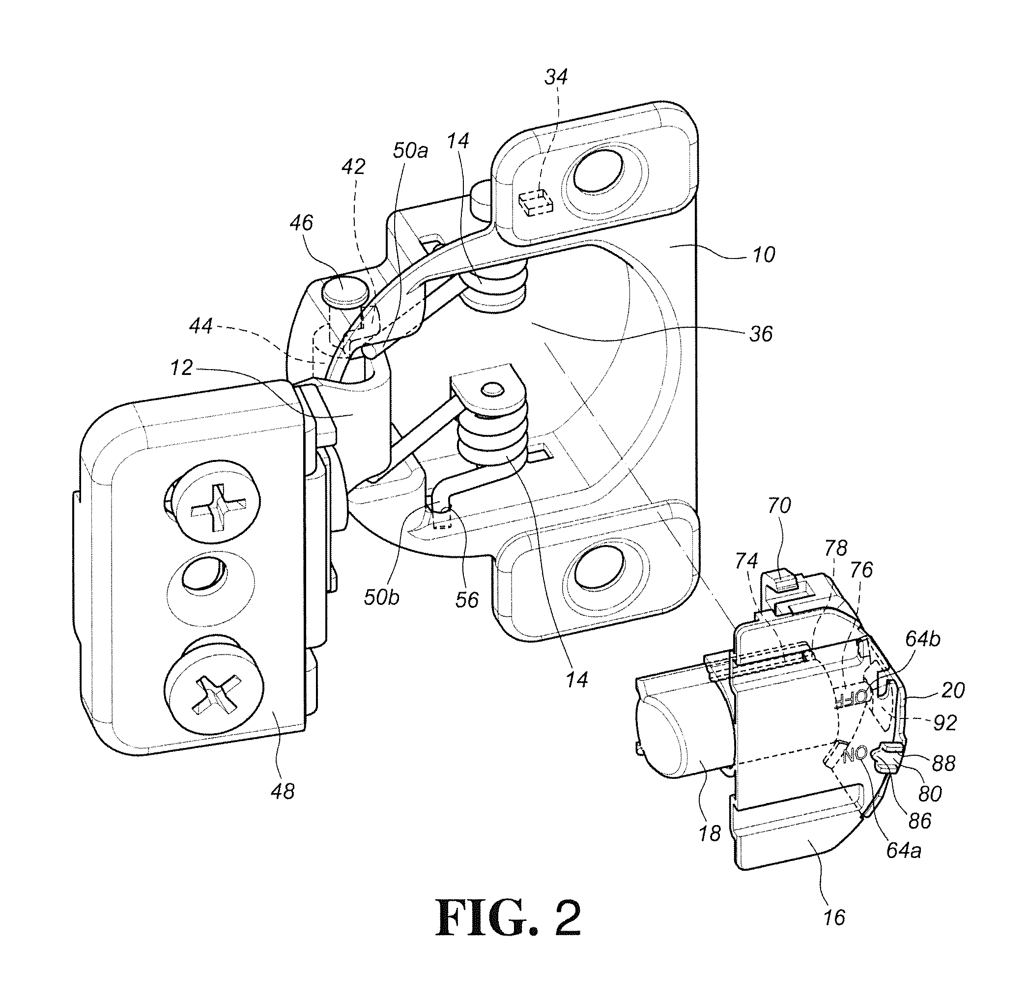
[0042]Referring to FIGS. 1 to 3, the hinge assembly of the present invention comprises a housing 10, an arm 12, at least one spring 14, a maintaining member 16, a damper 18 and an adjustment member 20.

[0043]The housing 10 comprises two side walls 22, an inner bottom 24, a front wall 26 and a rear wall 28, wherein the side walls 22 of the housing 10 have two pivotal holes 30, and the two pivotal holes 30 are located adjacent to the front wall 26. The side walls 22 further have two pin holes 32 and two positioning holes 34. The inner bottom 24 is connected between the two side walls 22. Preferably, the inner bottom 24 is connected to the side walls 22, the front wall 26 and the rear wall 28. The front wall 26 is connected to the front end of the two side walls 22, and the rear wall 28 is connected to the rear end of the side walls 22. The chamber 36 of the housing 10 is defined by the two side walls 22, the inner bottom 24, the front wall 26 and the rear wall 28. The inner bottom 24 h...


PUM


Abstract

A hinge assembly includes a housing, an arm and at least one spring. A damping device includes a damper having a piston rod, a maintaining member secured in the housing and an adjustment member. The adjustment member is movably connected to the maintaining member and has a protruded portion located corresponding to the piston rod of the damper. When the adjustment member is moved to a first position relative to the maintaining member, the protruded portion of the adjustment member is located toward the piston rod of the damper, so that the piston rod contacts the protruded portion and retracts to perform damping function. When the adjustment member is moved to a second position relative to the maintaining member, the protruded portion of the adjustment member is moved away from the piston rod of the damper, and no damping function is available.

Description

FIELD OF THE INVENTION[0001]The present invention relates to a damping device, and more particularly, to a damping device for a hinge assembly.BACKGROUND OF THE INVENTION[0002]WO / 2012 / 024702 A1 discloses a “DAMPING DEVICE FOR FURNITURE PARTS” and comprises a damping device used on furniture parts. The damping device 9 as disclosed in FIGS. 4a and 4b of the prior invention comprises a housing 12, a slider 13 and a locking device 15, wherein the slider 13 has a locking member 19 extending therefrom.[0003]FIG. 5a shows that there is a space between the piston 22 and the fluid chamber 21 of the slider 13, so that when the inclined abutment surface 16 of the slider is touched, the slider 13 moves relative to the piston 22 so as to have the damping feature.[0004]FIG. 5c shows that the locking element 15a of the locking device 15 contacts the locking member 19 of the slider 13, so that the slider 13 retracts relative to the piston 22 and is positioned. Therefore, as shown in FIG. 6b, the s...

Claims


Application Information

Patent Timeline
Patent Type & Authority Patents(United States)
IPC IPC(8): E05F1/08E05D11/10
CPCE05F5/006E05F5/02E05Y2201/21E05Y2201/256E05Y2201/264E05Y2201/212E05Y2201/244E05F5/04E05F2005/046E05Y2201/22E05Y2201/474E05Y2900/20E05Y2201/214
Inventor LIANG, HSIU-CHIANGCHEN, KEN-CHINGWANG, CHUN-CHIANGJHAO, YI-SYUAN
Owner KING SLIDE WORKS CO LTD
Learn More