
Dynamic damper for use in a drill string

a damping device and drill string technology, applied in the direction of drilling accessories, earthwork drilling and mining, borehole/well accessories, etc., can solve the problems of lifting and loosening the drill bit from the bottom, and achieve the effect of reducing the risk of the drill bit getting jammed

Active Publication Date: 2009-08-25
TOMAX
View PDF20 Cites 19 Cited by
  • Summary
  • Abstract
  • Description
  • Claims
  • Application Information

AI Technical Summary

Benefits of technology

[0007]In relation to prior art, the object of the invention is to provide a solution that reduces the risk of the drill bit getting jammed, and of accumulated energy stored as torque in the drill string being released in the form of uncontrolled rotation.
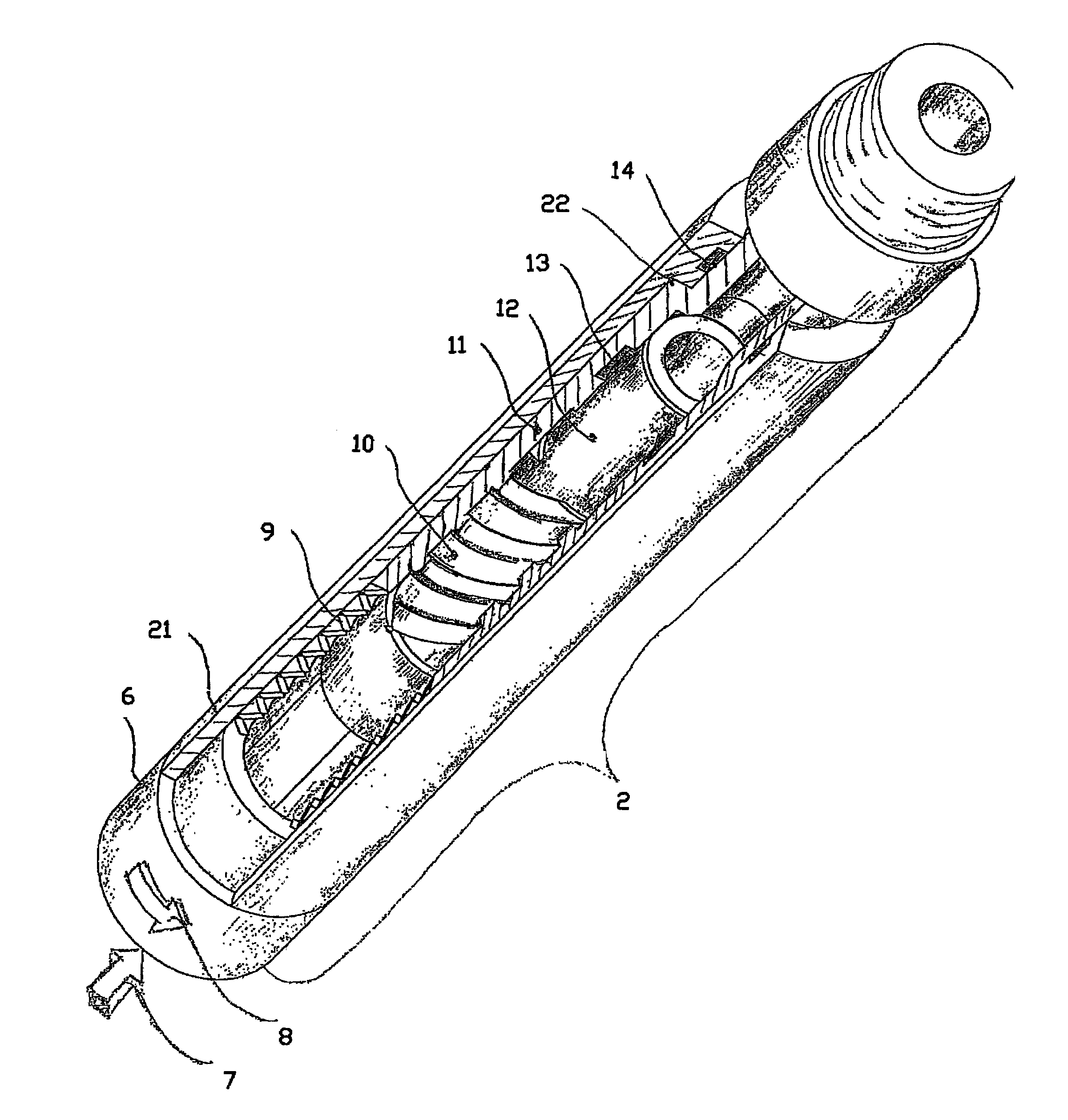
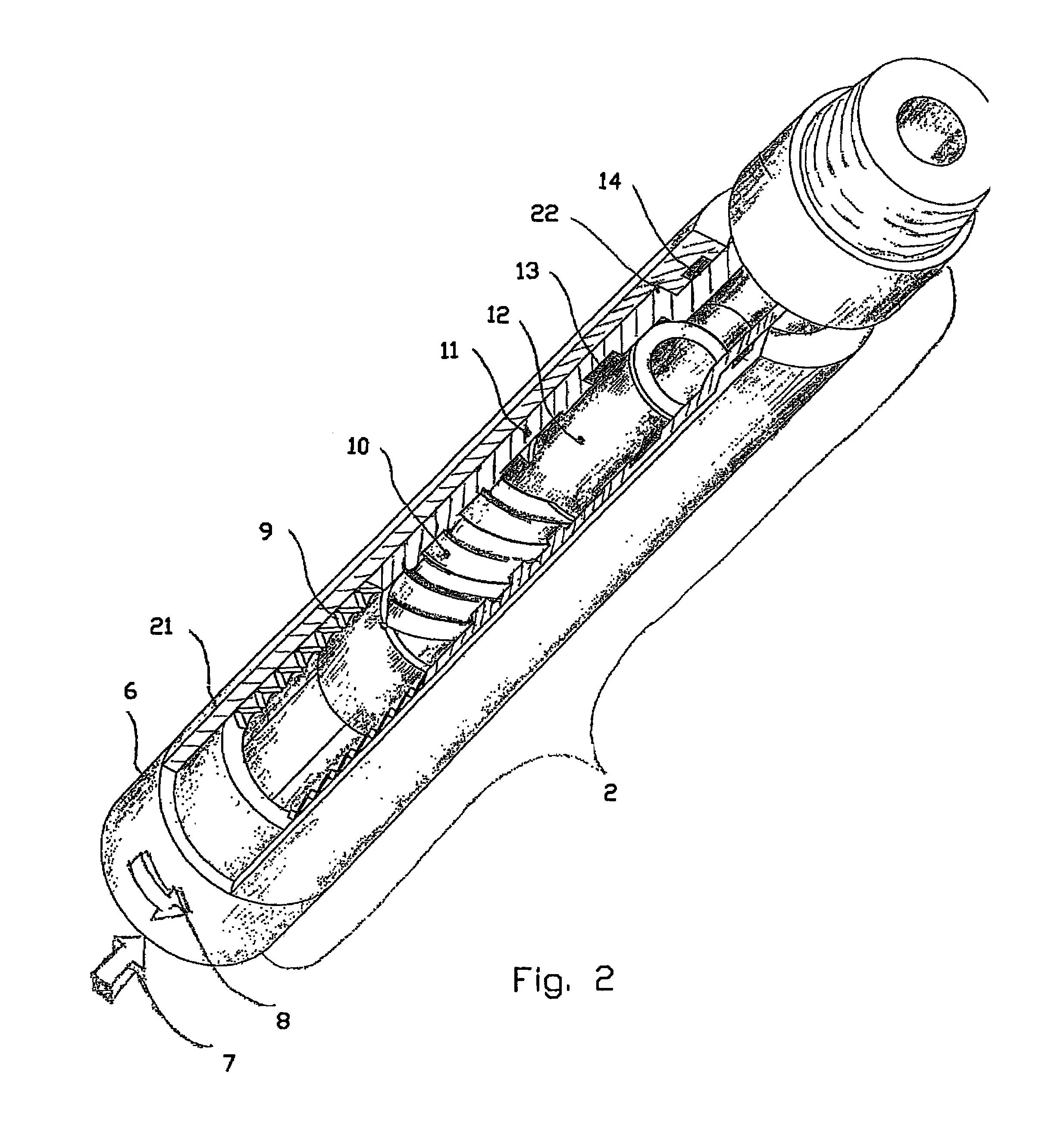
[0008]This is achieved in accordance with the invention, by a dynamic damper being installed in the drill string, above the measuring equipment used for directional control. This damper consists of an inner cylindrical string section with threads that connect this to the upper section of the drill string, which in turn is connected to the rotary machine on the surface. An outer cylindrical string section is supported concentrically on the inner string section and connected to a lower section of the drill string towards the drill bit, through a threaded connection. The outer and inner string sections are engaged through a spiral trapezoidal threaded connection, so that relative rotation between the string sections will cause a relative axial movement between the two parts. A spring is disposed between the outer and inner string sections and pre-tensioned, so that axial movement between the outer and inner string sections occurs only when axial force and moment or a combination of these exceed a predetermined value. Externally of the outer string section there is provided a cylindrical jacket connected to the inner string section through a threaded connection, such that the jacket protects the outer and inner string sections while at the same time constituting a limitation for the axial movement between the outer and inner string sections.
[0010]When the present invention is installed in a drill string, torque caused by incipient locking of the drill bit will effect relative rotation between the outer and inner string sections when the moment exceeds a selected spring tension. This will result in an axial movement that lifts and loosens the drill bit from the bottom. When the drill bit comes loose, the moment is reduced and the spring will again push the drill bit towards the bottom of the borehole, thus generating torque resistance that prevents the accumulated torque in the drill string from “spinning” out of control.

Problems solved by technology

This will result in an axial movement that lifts and loosens the drill bit from the bottom.

Method used


Image

  • Dynamic damper for use in a drill string
  • Dynamic damper for use in a drill string
  • Dynamic damper for use in a drill string

Examples


Embodiment Construction

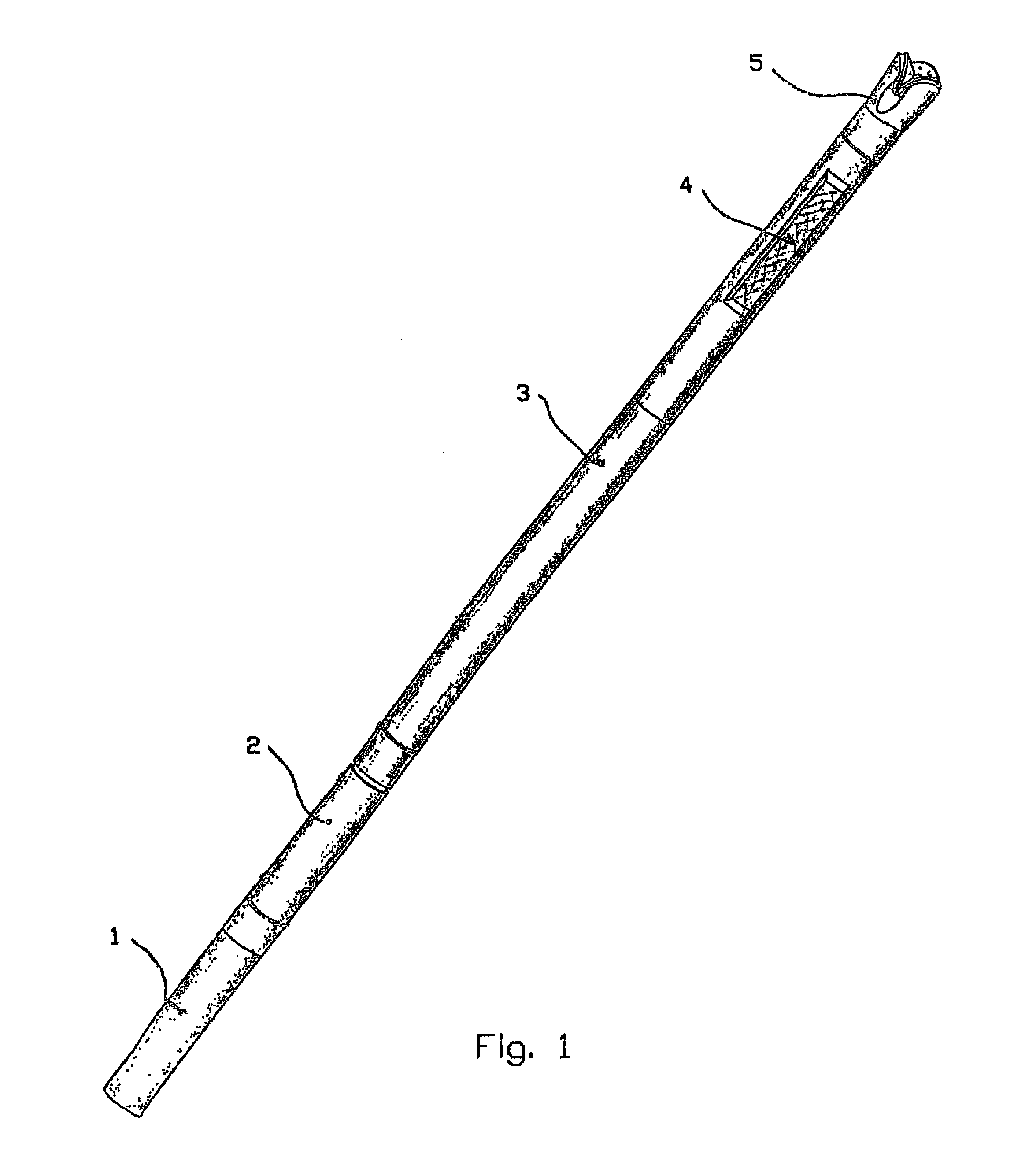
[0015]In the drawings, reference number 1 denotes a known drill string where the dynamic damper has been installed and is referred to by reference number 2. The instrumentation section for directional control 3 is installed in an extension of the damper, towards the drill bit, while the extension of part 3 holds stabilizers nibs 4 and drill bit 5.

[0016]The torque and the axial force transferred to the damper are indicated by reference numbers 8 and 7. The end piece 6 attached to the drill string with a threaded connection transfers the forces to an inner string section 12.

[0017]The inner and outer string sections are engaged through helical threads 10, such that relative rotation of these parts will entail relative axial movement between the parts. A torsional spring 9 stops against the end piece 6 on the inner string section 12 and against the outer string section 11. The spring forces the outer string section 11 to stop against the shoulder 22 of outer jacket 21. Thus the outer st...


PUM


Abstract

A dynamic damper for installation in a drill string (1), the purpose of which damper is to reduce the risk of jamming the drill bit (5), thereby avoiding damages in the event of unwanted extreme oscillations and rotational speed of the drill string caused by uncontrolled release of torsional energy in the drill string when the drill string suddenly breaks free of the jam. For this purpose, the damper is constructed from an outer and an inner string section (11) and (12), supported concentrically and interconnected through a helical threaded connection (10), so that relative rotation between the sections caused by torque (8) will give an axial movement that lifts and loosens the drill bit from the bottom of the hole in critical jamming situations. The spring (9) maintains the outer string section in an axial position against the shoulder (22). A hydraulic damping effect on the axial movements is achieved by oil volumes (16) and (17) being interconnected through narrow bores (18). Logging of the damping function is carried out by sensor (20), which registers and stores data to be read when the damper is retrieved to the surface.

Description

CROSS REFERENCE TO RELATED APPLICATION[0001]The present application is the U.S. national stage application of International Application PCT / NO2003 / 000121, filed Apr. 14, 2003, which international application was published on Oct. 21, 2004 as International Publication WO 2004 / 090278.BACKGROUND OF THE INVENTION[0002]This invention regards a dynamic damping device for use in a drill string, designed especially for use when drilling for hydrocarbons in sedimentary rocks.[0003]Known dynamic dampers are extensively used to dampen oscillations that arise in mechanical constructions subjected to variable loads. In a drill string having a length of several thousand metres, oscillations can arise as a result of variations in the torque along the drill string.[0004]Variations in torque may be due to different frictional conditions along the string and drilling through formations of different hardness, causing the moment on the drill bit to vary. Such uncontrollable variations in torque will in...

Claims


Application Information

Patent Timeline
Patent Type & Authority Patents(United States)
IPC IPC(8): E21B17/07
CPCE21B17/073
Inventor HAUGHOM, PER OLAV
Owner TOMAX
Learn More