Apparatus for removing debris from gutters, troughs and other overhead open conduits

a technology for removing debris and debris from gutters, troughs and other overhead open conduits, which is applied in the direction of chemistry apparatus and processes, cleaning using liquids, cleaning equipment, etc., can solve the problems of reducing the strength of the vacuum available, heavy devices and difficult to carry, and previous devices are problematic, etc., to achieve tight seals, easy to determine, and improve cleaning

Inactive Publication Date: 2013-10-22
LOWENSTEIN ARNOLD
View PDF16 Cites 14 Cited by
  • Summary
  • Abstract
  • Description
  • Claims
  • Application Information

AI Technical Summary

Benefits of technology

[0014]Typically a handle is attached to the main body of the shaped conduit so that the positioning of the conduit relative to the overhead open conduit is easier and more precise. The on-off switch for the vacuum and the open-close valve for the water supply line are typically located next to the handle, if not on the handle, for ease of use. The opening in the lower, straight part of the shaped conduit is configured to fit into a coupling, or may include a coupling which enables the lower part of the shaped conduit to be attached to a flexible hose which leads to the shop vacuum or other source of vacuum. The flexible hose is sized to be large enough to handle accumulations of debris on its way to the vacuum source.
[0015]In one embodiment of the apparatus, which is advantageous when the overhead open conduit to be cleaned is higher off ground level, such as when the open conduit is two stories high, the shaped section of the conduit is shorter, and hose which is coupled to the shop vacuum or other source of vacuum travels the majority of the distance from the open conduit to the ground level. This reduces the amount of weight the user must carry. To permit control over the shaped conduit portion of the apparatus, a long handle is attached to the shaped conduit adjacent to the opening at the lower portion of the shaped conduit. Typically there is a collar around the bottom portion of the conduit and the handle is attached to the collar. There is an adjustable swivel joint at the top of the handle which is attached to the collar, and the swivel joint permits the user to manipulate the position of the shaped conduit relative to the overhead open conduit. The handle may be a telescoping handle, of the kind used in the painting industry, for example, to permit setting of the length of the handle to a convenient length. In the alternative, sections of handle may be fastened together using receptors at the ends of the sections, so that a desired length may be obtained. The water line to the water spray is coupled to a flexible, typically coiled hose which leads down to the handle, where a coupling is provided to the handle. The on-off valve for the water supply is located near the bottom of the handle, adjacent the on-off switch for the vacuum.
[0017]There are a number of attachments which may be applied to the top opening in the shaped conduit which reaches into the overhead open conduit. These attachments may be of various shapes to enable the better cleaning of typical open conduits used for water transport. The portion of the attachment which contacts the surface of the open conduit are typically beveled in a manner which prevents a very tight seal between the attachment surface and the open conduit surface, which would make it difficult to move the apparatus along the open conduit during cleaning. In addition, a scraping device, which fastens to at least the leading edge of the attachment, may be removably attached to a basic attachment. Preferably the scraping device can be snapped or slid into place over the edge of the attachment.
[0018]The design of the apparatus makes it possible to periodically apply the vacuum to the apparatus as a means of breaking up blockages present within the apparatus which may prevent flow of the debris from the collection point at the open end of the shaped conduit present in the overhead open conduit to a collection vessel in which the debris is to be accumulated. As previously discussed, an on-off switch to the vacuum source and a valve to the water supply are placed at a location which enables the operator to reach them easily, with both typically being placed on or adjacent to the handle of the apparatus. Either of the on-off switch to the vacuum supply source, or the water supply valve, or a combination of both may then be periodically applied to cause a surge of the materials (water and debris) present in the debris movement path. This surge of vacuum, or surge of water, or a combination of surging vacuum and surging water (where the surges are simultaneous or offset) can be used to dislodge blockages in the debris movement path toward the debris collection vessel. Offset surges of vacuum and water may be overlapped. The frequency with which the vacuum application or the water application needs to be turned on or off will depend on the kind of debris which is present in the overhead open conduit, and can be easily determined by minimal experimentation of the operator of the apparatus.

Problems solved by technology

However, the previous devices have been problematic, particularly when the debris to be removed includes pine needles or twigs in combination with the leaves and dirt which gradually accumulate, particularly in the fall of the year.
Many of the previous devices include motors or other features which make the device heavy and difficult to carry.
This reduces the strength of the vacuum available to move the debris along its way to the collection area of the vacuum cleaner.
During operation, wet debris is said to fall into the canister where it is collected.
The canister is shown to have a motorized impeller, and the complete system appears to be bulky and problematic to manipulate.
This unit also appears to be very bulky, heavy and complex to operate.
The apparatuses vary in complexity; however, all of the apparatuses include a source of vacuum, a rigid conduit which makes direct contact with the gutter, and a flexible hose from the conduit to the vacuum source.
However, the mechanical devices which are used to break up the debris are relatively complicated and add weight to the top portion of the conduit, making the apparatus heavier and more difficult to control, since this weight is at the end of a long pole or conduit which is high in the air.

Method used


Image

  • Apparatus for removing debris from gutters, troughs and other overhead open conduits
  • Apparatus for removing debris from gutters, troughs and other overhead open conduits
  • Apparatus for removing debris from gutters, troughs and other overhead open conduits

Examples


Embodiment Construction

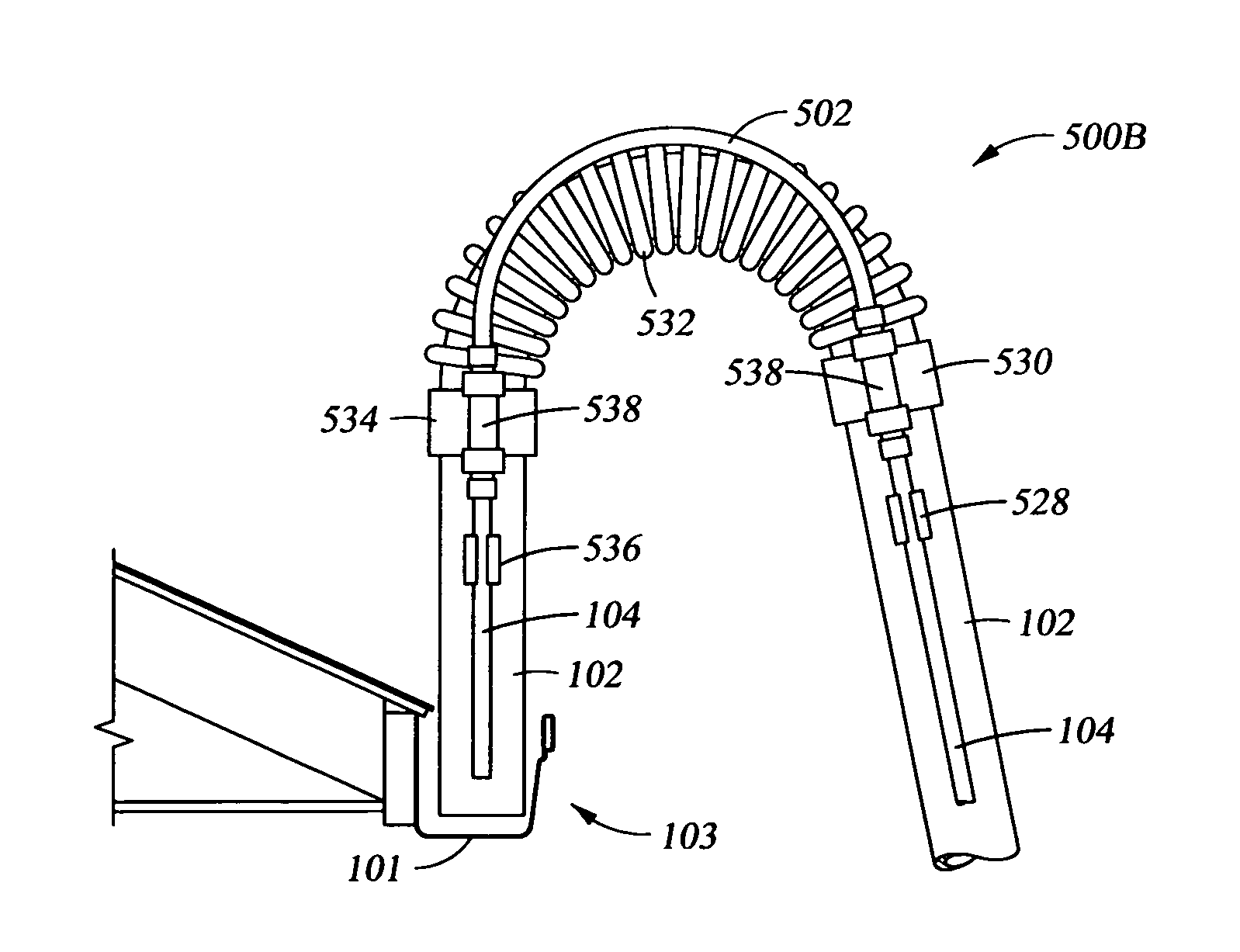
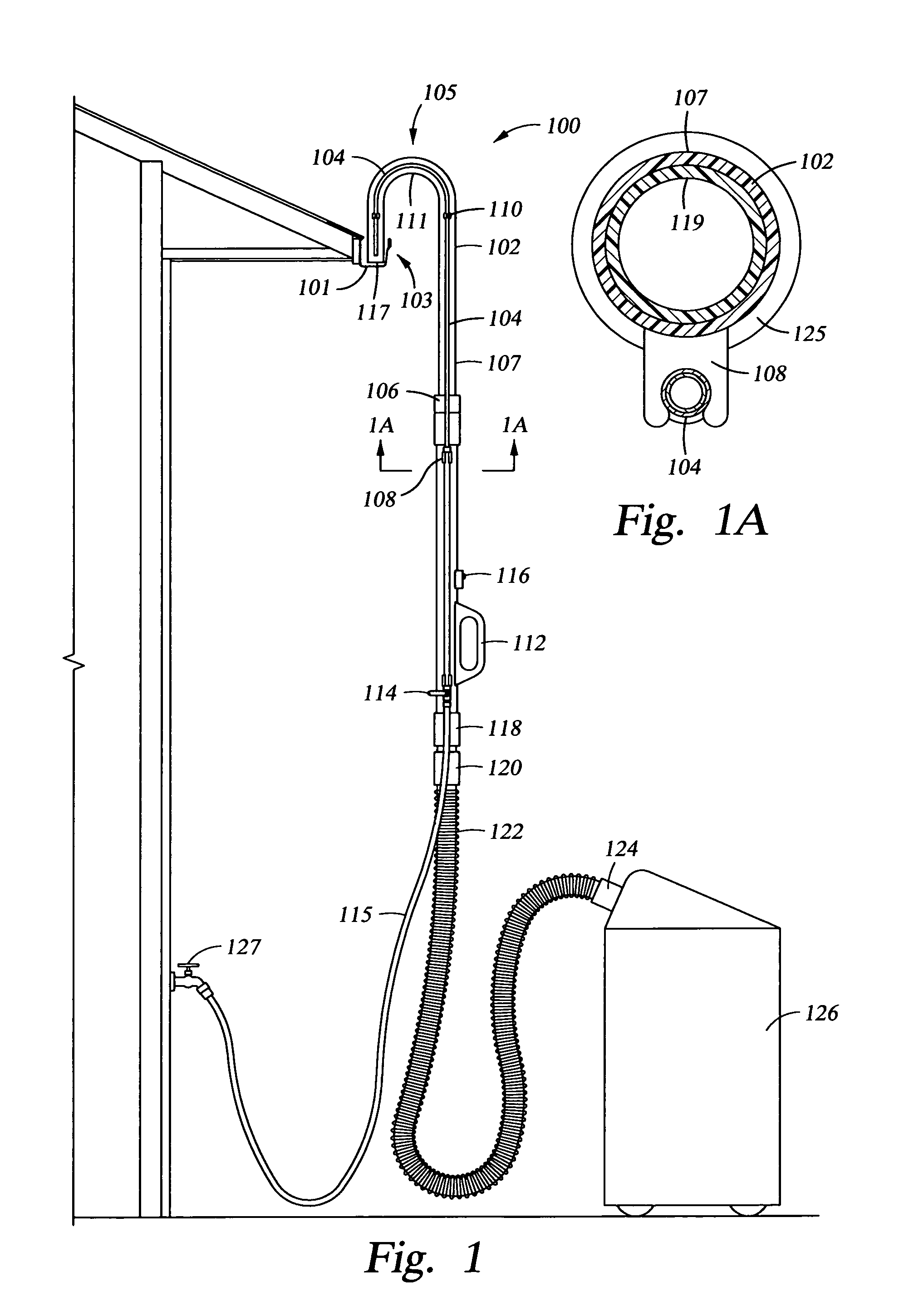
[0035]The apparatus can be used to remove debris from gutters, troughs, and other overhead open conduits used for water flow. With reference to FIG. 1, the apparatus 100 includes a shaped conduit 102 where the sidewalls are closed and each end of the conduit is open. The main body 107 of the conduit is straight, with an opening at the bottom (not shown), and an opening 117 from the upper portion 105 of the shaped conduit 102, which reaches from the main body 107 into the gutter, trough or other overhead open conduit 103, exhibits a bend 111 which allows the shaped conduit 102 to reach over the edge of overhead open conduit 103, so that the end 117 of the upper portion 105 of the conduit is adjacent the bottom 101 of the overhead open conduit 103, where the debris (not shown) to be removed is present. A second water line 115, typically extends from water line 104 to a water source such as water spigot 127. The flow of water through the shaped conduit 102, and flexible line 122 to col...


PUM


Abstract

The apparatus removes debris from overhead open conduits. The apparatus includes a shaped conduit with closed sidewalls. The top portion of the shaped conduit exhibits a bend which permits it to reach into the open conduit. The portion of conduit beneath the bend is straight. On the straight portion there is an on-off switch which sends a wireless signal to a switch on a source of vacuum which is attached to the straight portion. Adjacent the on-off switch there may be a valve which controls an amount of water applied from a water line attached to the shaped conduit.

Description

FIELD OF THE INVENTION[0001]Embodiments of the present invention relate to an apparatus useful in removing debris such as pine needles, leaves and sludge from gutters, troughs and other overhead open conduits for water flow.BACKGROUND OF THE INVENTION[0002]This section describes background subject matter related to the disclosed embodiments of the present invention. There is no intention, either express or implied, that the background art discussed in this section legally constitutes prior art.[0003]Gutter cleaning devices have been available prior to the present apparatus. A number of devices have attempted to provide a means of removing leaves and other debris which form a semi-solid sludge within a gutter. However, the previous devices have been problematic, particularly when the debris to be removed includes pine needles or twigs in combination with the leaves and dirt which gradually accumulate, particularly in the fall of the year. Many of the previous devices include motors o...

Claims


Application Information

Patent Timeline
Patent Type & Authority Patents(United States)
IPC IPC(8): B08B3/04B08B3/00
CPCB08B5/04E04D13/0765
Inventor LOWENSTEIN, ARNOLD
Owner LOWENSTEIN ARNOLD
Why Eureka
Try Eureka