Self propelled kit applicable to buckraking machines or silo-bag

a kit and buckraking machine technology, applied in the field of self-propelled kits, can solve the problems of generating delays, inability to use, and inability to carry out grain silage without a tractor or the like, and achieve the effect of convenient adaptation

Inactive Publication Date: 2013-10-22
MAMARELLA OSCAR ALFREDO 30 +2
View PDF8 Cites 1 Cited by
  • Summary
  • Abstract
  • Description
  • Claims
  • Application Information

AI Technical Summary

Benefits of technology

[0005]The present invention comprises a kit which can be easily adapted to any buckrake in the market, and allows people to work without using the tractor, leaving it for other tasks.
[0007]It is known in the art to use buckraking devices that do not use tractors and where the grain is loaded into the silo-bag by gravity. Those machines do not obtain successful grain storage and result in totally discarded grains with low specific gravity. Therefore, the result is a low percentage of bag storage and waste of the bag's volume.
[0008]The present set of elements guarantees a total and effective storage of bags, permits its use with any dry grain, replaces the use of the tractor, attaining the worm gear's movement and self-propulsion through a 13 HP engine, a hydraulic automatic clutch, a coupling fuse, a speed reducer gear, and a short cardan joint. Likewise, a much softer, uniform and without vibrations bag storage is obtained, since the transmission cardan joint was shortened.
[0010]The directional wheel of the buckraking device will be constituted by a wheel made of a disc-shaped central sheet with two cylindrical bodies as wheels by each side. The previously mentioned disc will stick in the ground and it will allow the machine to be directed in all types of land. The cylindrical bodies will include wings for a better adherence to the ground.

Problems solved by technology

It should be clear that it is not possible to carry out grain silages without a tractor or the like, since neither the worm gear would be moved nor would it allow the buckraking device to advance in the desired direction.
The great disadvantage which arises with the need to use a tractor is that it cannot be used for other important tasks such as silage, generating delays as a consequence.

Method used


Image

  • Self propelled kit applicable to buckraking machines or silo-bag
  • Self propelled kit applicable to buckraking machines or silo-bag
  • Self propelled kit applicable to buckraking machines or silo-bag

Examples


Embodiment Construction

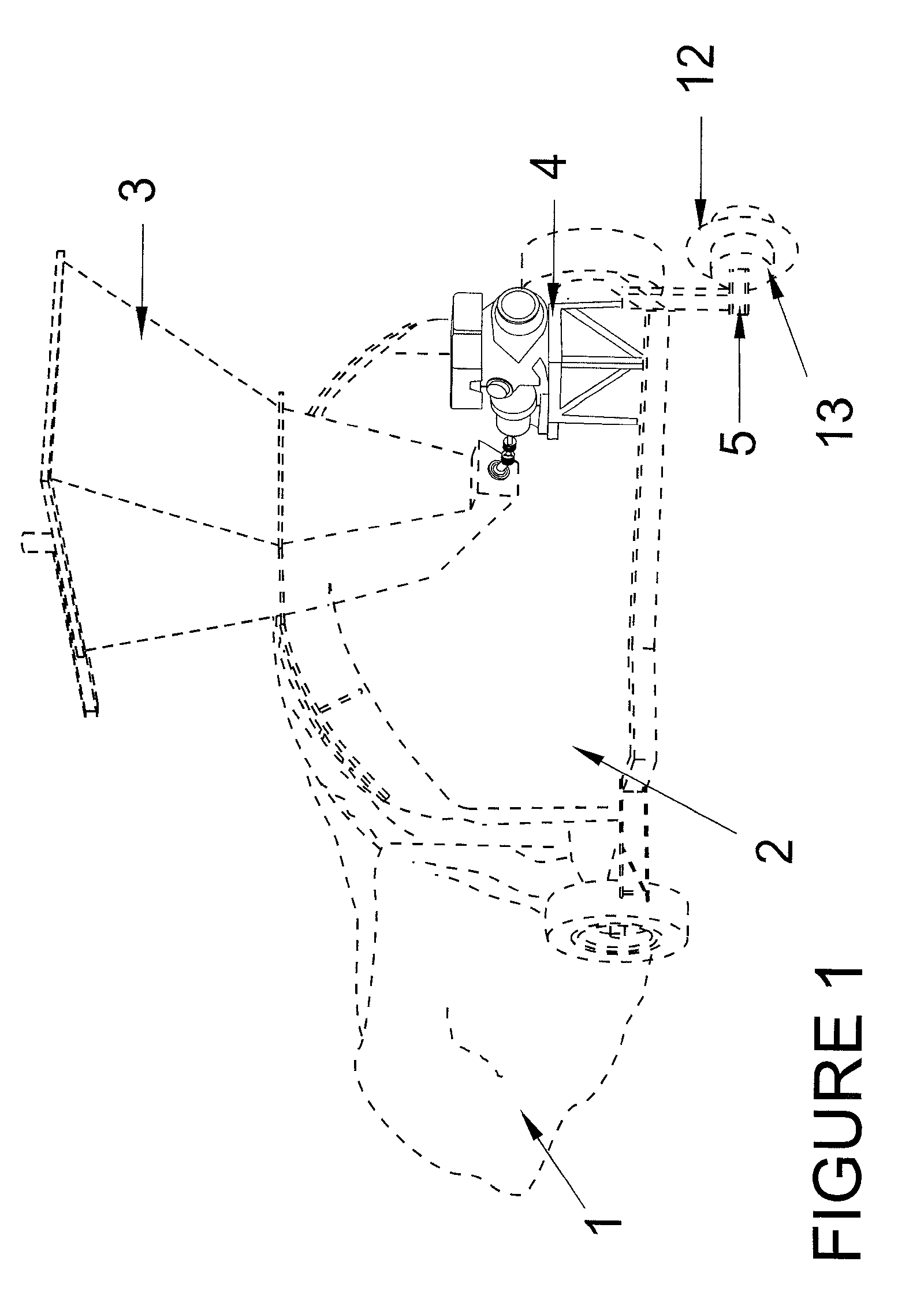
[0017]In FIG. 1 it can be observed an agricultural buckrake with its corresponding bag or silo-bag 1, fitted to the filling tunnel 2, the reception hopper 3, the activation engine 4 of the worm gear, and the direction wheel 5. It can be seen in the direction wheel 5, the central disc 12 and the cylindrical bodies 13 in each of the two lateral sides.

[0018]Hold wings may be placed perpendicular to the surface of rotation of the cylindrical bodies 13.

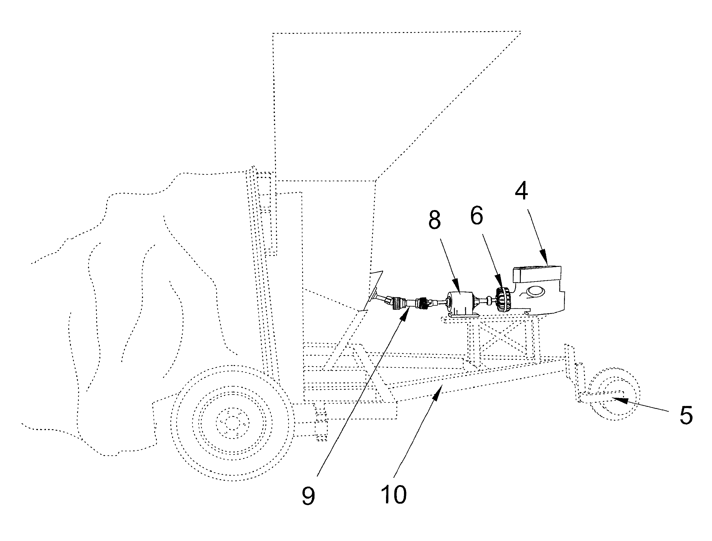
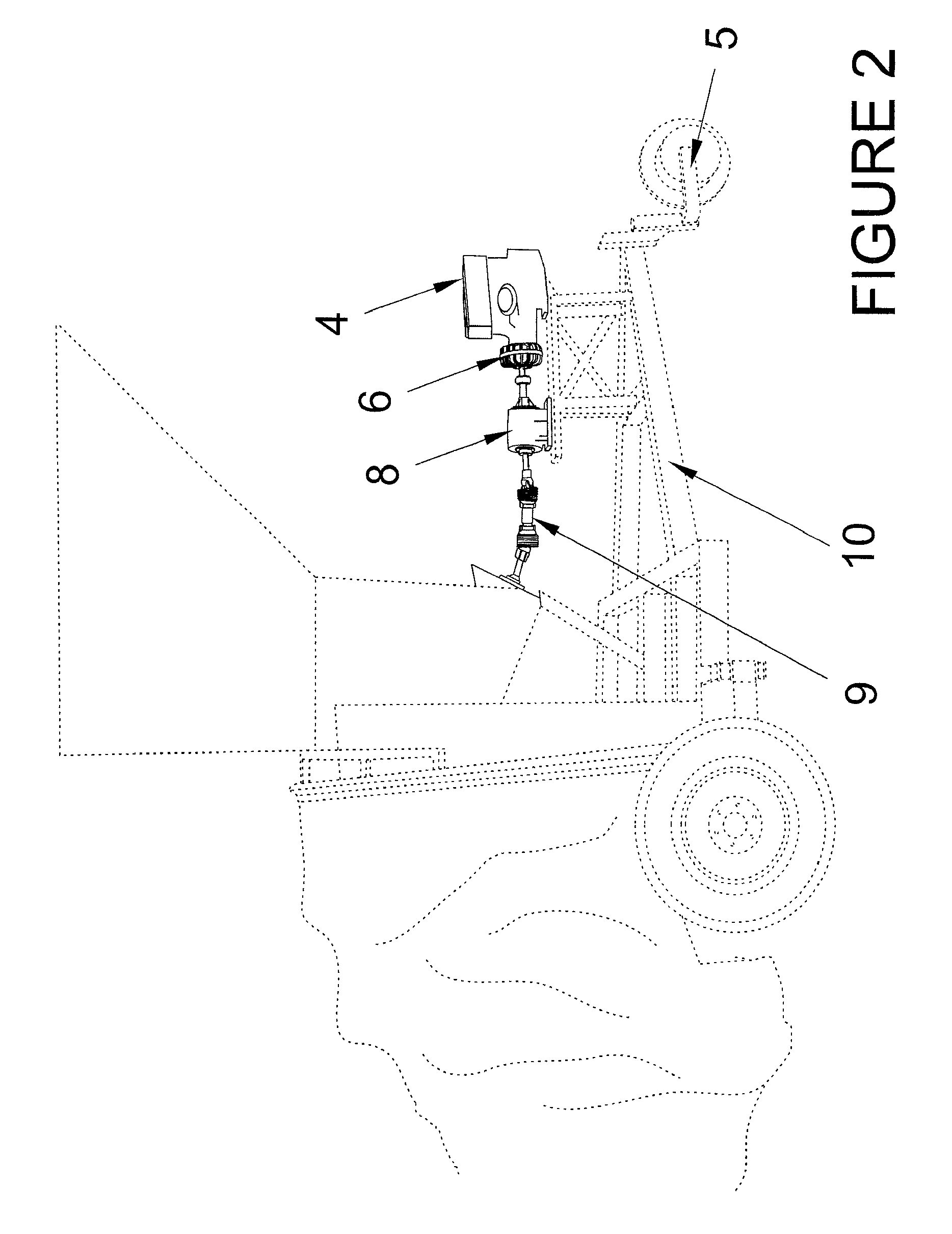
[0019]In FIGS. 2 and 3 it is illustrated in detail the engine 4 and its accessories through which movement to the loading worm gear of the buckrake is transmitted. The engine 4 is fitted to a clutch 6, preferably hydraulic and automatic, which fits to a coupling fuse 7, from there to a speed reducer 8, and from it a short cardan joint 9. The shortness of the joint offers the advantage of producing less vibration during the whole task. The above mentioned components are assembled on a base 11 which is shaped on the work spear 10.

[0020]Prefe...


PUM

PropertyMeasurementUnit
pressureaaaaaaaaaa
energyaaaaaaaaaa
speedaaaaaaaaaa

Abstract

The present invention relates to a kit which can be easily adapted to a buckraking device or silo-bag, to allow people to work without using a tractor. The kit includes a movable base having at least one wheel and an independent engine mounted on the movable base. The independent engine activates the load screw and a clutch mechanism is coupled to the independent engine. A coupling fuse is coupled to the clutch mechanism and a speed reducer is coupled to the coupling fuse. A short cardan joint is coupled to the speed reducer at one end and to the hopper in the other end.

Description

TECHNICAL FIELD[0001]The present invention relates to a self-propelled kit applicable to agricultural buckraking devices or silo-bags, the type which is utilized for grain storage in fields, and which includes a reception hopper, a filling tunnel, a worm gear or load screw for the filling of the connected bag.BACKGROUND OF THE INVENTION[0002]Grain buckraking devices that are currently known are those which carry out the grain storage, dependent on the use of a tractor or a similar vehicle. This vehicle is connected to the machine at the moment of working and through a transmission or cardan joint, which receives the tractor command, gives movement to the worm gear through the force bar, and control of the advance direction through its steering wheel and wheels.[0003]It should be clear that it is not possible to carry out grain silages without a tractor or the like, since neither the worm gear would be moved nor would it allow the buckraking device to advance in the desired direction...

Claims


Application Information

Patent Timeline
Patent Type & Authority Patents(United States)
IPC IPC(8): B65B1/20B65B3/18B65B3/16
CPCA01D69/00A01D69/08A01F25/183A01F2025/145
Inventor MORICI, SABRINA
Owner MAMARELLA OSCAR ALFREDO 30
Why Eureka
Try Eureka