Light emitting module device, light emitting module used in the device, and lighting apparatus provided with the device

a technology of light emitting modules and light emitting modules, which is applied in the direction of electroluminescent light sources, electrical lighting sources, and use of semiconductor lamps. it can solve the problems of increasing the amount of supply power flowing in the power lines, increasing the radiation noise of the supply power, and increasing the production cost. , to achieve the effect of reducing the number of lines, improving the signal accuracy, and reducing production costs

Inactive Publication Date: 2013-10-22
PANASONIC CORP
View PDF12 Cites 14 Cited by
  • Summary
  • Abstract
  • Description
  • Claims
  • Application Information

AI Technical Summary

Benefits of technology

[0014]An object of the present invention is to provide: a light emitting module device that is capable of individually controlling a plurality of light emitting modules, and that can reduce the production cost with a decreased number of lines and improve the accuracy of a signal to each light emitting module; and a lighting apparatus including the light emitting module device.
[0026]In the light emitting module device configured as described above, a control signal is superimposed onto power supplied via the power line to each of the light emitting modules, and the each light emitting module reads the control signal and lights up in accordance with the read control signal. Thus, the light emitting modules can be individually controlled. In addition, since the power line can be also used as communication lines, the number of lines can be decreased, and therefore, the production cost can be reduced. In addition, since the power line is shared by a plurality of the light emitting modules, the number of lines can be further decreased. Also, since a control signal is superimposed onto supply power in the extinction period in which power supplied to the light emitting module is substantially zero, the light emitting module can easily read the control signal. Therefore, signal communication is ensured, and the accuracy of signal communication can be improved.
[0035]the signal generation unit controls the open / close operations of the switches, thereby causing the column communication line and the row communication line for the light emitting module that is to be controlled, to be in conductive states, and causing the other column communication lines and the other row communication lines to be in non-conductive states, and transmits the control signal to the light emitting module to be controlled.
[0036]In the light emitting module device configured as described above, the switches provided on the communication lines are controlled so as to be opened or closed, and only the light emitting module to be controlled is electrically connected to the signal generation unit. Then, a control signal is transmitted from the signal generation unit to the light emitting module to be controlled. Therefore, the light emitting modules can be individually controlled. In addition, since the communication lines are shared by a plurality of the light emitting modules, the number of lines decreases, and the production cost can be reduced. In addition, since the communication lines are used only for transmitting a control signal, the transmission power that is needed decreases. Therefore, the radiation noise decreases, and the influence of the radiation noise on a control signal can be suppressed. Therefore, the accuracy of control of the light emitting modules increases.
[0044]In the light emitting module device configured as described above, when a plurality of the light emitting modules are arranged so as to be adjacent to each other, the positive terminals for communication of the respective light emitting modules are connected to each other, and the negative terminals for communication of the respective light emitting modules are connected to each other, whereby communication paths are formed among a plurality of the light emitting modules. Therefore, a control signal transmitted from the control unit can be transmitted to a plurality of the light emitting modules via the communication paths, and thus, the number of lines through which the control signal is transmitted can be reduced.

Problems solved by technology

However, since the control apparatus is provided in each of the light emitting modules 101, the production cost increases.
However, in such a light emitting module device, supply power to a plurality of light emitting modules flows in power lines, and as a result, the amount of the supply power flowing in the power lines increases.
Therefore, if the supply power is sequentially changed for individually controlling the light emitting modules, increased radiation noise can be superimposed onto the supply power.
The radiation noise is superimposed onto the control signal, and therefore, there is a possibility that the light emitting modules cannot be accurately controlled.
However, in the light emitting module 400 described above, the control apparatus 402 of each light emitting module 400 needs to have a function of generating a control signal, and as a result, the cost increases.
As a result, the cost of a lighting apparatus increases because of a complicated providing method of the IDs.

Method used


Image

  • Light emitting module device, light emitting module used in the device, and lighting apparatus provided with the device
  • Light emitting module device, light emitting module used in the device, and lighting apparatus provided with the device
  • Light emitting module device, light emitting module used in the device, and lighting apparatus provided with the device

Examples


first embodiment

Second Variation of First Embodiment

[0094]A light emitting module device according to the second variation of the first embodiment will be described. Since the configuration of the light emitting module device is the same as that of the first embodiment, FIGS. 1 and 2 are also used in the description below. In the present variation, the lighting control circuit 22 of the light emitting module 2 does not have a capacitor which extends the operation period after supply of power is stopped. If supply of power is stopped during a predetermined period or longer, the setting is reset.

[0095]FIG. 6 shows switching operations of the column switches 31a to 31d and the row switches 32a to 32d for which open / close control is performed by the signal generation circuit 43 of the present variation. In FIG. 6, a control signal is to be transmitted only to the light emitting module 2A (see FIG. 3(a)).

[0096]One of the column switch 31a and the row switch 32a for the light emitting module 2A changes f...

second embodiment

Variation of Second Embodiment

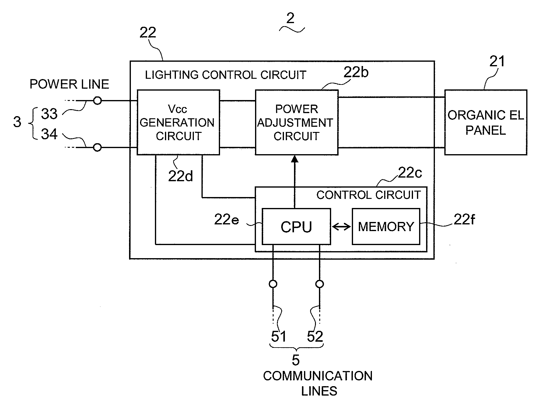
[0124]FIG. 14(a) shows the circuit configuration of the light emitting module 2 according to a variation of the second embodiment, and FIG. 14(b) shows the voltage waveforms at various sections of the circuit. In the present variation, the control circuit 22c of the lighting control circuit 22 of the light emitting module 2 includes a charge / discharge circuit (memory unit) in place of the CPU 22e and the memory circuit 22f of the second embodiment. The charge / discharge circuit retains a control signal Va inputted from the signal generation circuit 43 during a predetermined retaining period. The charge / discharge circuit controls the operation of the power adjustment circuit 22b, based on the control signal Va stored in the charge / discharge circuit, thereby adjusting an output voltage Vout to the organic EL panel 21. The charge / discharge circuit is volatile, so that if the retaining period has passed, the charge / discharge circuit loses the control signal....

third embodiment

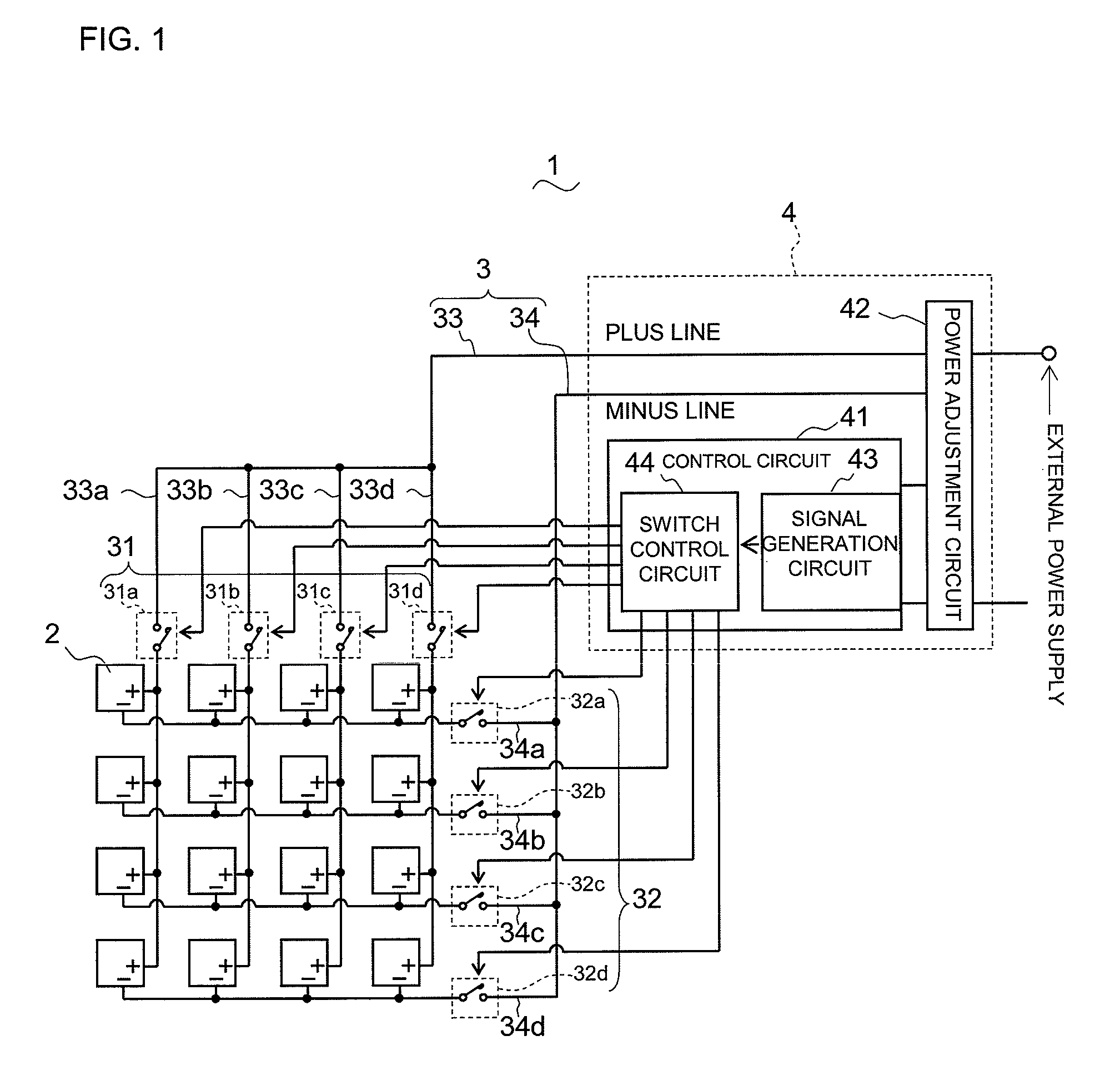
[0130]FIG. 15 shows the configuration of a light emitting module device according to the third embodiment of the present invention, and FIGS. 16(a) and 16(b) show the configuration of a light emitting module used in the light emitting module device. The light emitting module device 1 of the present embodiment includes light emitting modules 6 in place of the light emitting module 2 in the light emitting module device 1 of the second embodiment, and the other components of the present embodiment are the same as those of the second embodiment.

[0131]The light emitting module 6 includes a planar light emitting device 61, feed terminals 62, a rectangle panel 63, a lighting control circuit 64, a plurality of communication positive terminals 65, and a plurality of communication negative terminals 66. The planar light emitting device 61 has a light emitting layer sandwiched between the electrodes thereof. The feed terminals 62 as a pair of terminals are connected to the output terminals of ...


PUM


Abstract

A light emitting module device includes: a power line through which power is supplied to light emitting modules; and a signal generation circuit which generates a control signal. The power line is shared by a plurality of the light emitting modules, and has switches and switches which turn on or off current conduction to the light emitting modules, through open / close operations. The signal generation circuit individually controls the switches and the switches. The open / close operations include a light-emission period in which the light emitting module emits light; and an extinction period in which the light emitting module is extinguished, and if there is a control signal to be transmitted to the light emitting module, the control signal is superimposed onto supply power. Since a control signal is superimposed onto supply power to each light emitting module, the light emitting modules can be individually controlled. In addition, since the power line can be used also as a communication line, and the power line can be shared by a plurality of the light emitting modules, the number of lines can be decreased.

Description

TECHNICAL FIELD[0001]The present invention relates to a light emitting module device that individually controls a plurality of light emitting modules, a light emitting module used in the light emitting module device, and a lighting apparatus provided with the device.BACKGROUND ART[0002]FIG. 17 shows the configuration of a conventional light emitting module device. In a light emitting module device 100, light emitting modules 101 are arranged in a matrix, the light emitting modules 101 adjacent to each other are connected via connection points 102 for transmitting power, and a terminating apparatus 104 for a power line 103 is attached to the light emitting modules 101 at one end column. Each of the light emitting modules 101 has a control apparatus (not shown) which adjusts the light emission amount of the light emitting module 101 by itself. When the terminating apparatus 104 supplies power to the light emitting modules 101, power is sequentially transmitted to the light emitting mo...

Claims


Application Information

Patent Timeline
Patent Type & Authority Patents(United States)
IPC IPC(8): H05B37/02H05B44/00
CPCH05B33/0824H05B33/0845H05B37/0263H05B33/086H05B33/0803H05B45/44H05B47/185H05B45/00H05B45/10H05B45/325H05B45/60Y02B20/30
Inventor OKAWA, MASANAOKONISHI, HIROFUMIYAMAMOTO, SHOHEIYAMAUCHI, KENTARO
Owner PANASONIC CORP
Why Eureka
Try Eureka