
Method of optimizing a flight plan

a flight plan and flight management technology, applied in the direction of navigation instruments, instruments, energy saving arrangements, etc., can solve the problems of aircraft departing from the optimal flight plan, increased operating costs, positive cost differentials, etc., and achieve the effect of optimizing the cost index

Inactive Publication Date: 2013-10-22
THALES SA
View PDF16 Cites 19 Cited by
  • Summary
  • Abstract
  • Description
  • Claims
  • Application Information

AI Technical Summary

Benefits of technology

This approach allows the flight management system to minimize deviations from the optimal cost index by recomputing flight strategies in real-time, ensuring closer adherence to the operator's optimal cost index even with external constraints, thereby optimizing flight plans and reducing operational costs.

Problems solved by technology

However, during a mission, additional temporary constraints of air traffic management or constraints imposed by the crew, may cause the aircraft to depart from the optimal flight plan.
These effects will often result in an increased operating cost (a positive cost differential) that is an increasing function of the delay.
But the current flight management systems are not able to take account of the optimal cost index CI determined by the operator for a given mission, to generate a corresponding optimal flight plan with notably an estimate of the time on arrival and of the fuel remaining on arrival.
Therefore, modifications of the flight plan during the mission that cause a non-adherence to the arrival timeslot may not be taken into account by these systems, which results on arrival in a real cost index CIr that is different from the optimal value CIopt determined by the operator.
And the flight management system has no means that could make it possible to return to the CT and CF indices from the CI.

Method used


Image

  • Method of optimizing a flight plan
  • Method of optimizing a flight plan
  • Method of optimizing a flight plan

Examples


Embodiment Construction

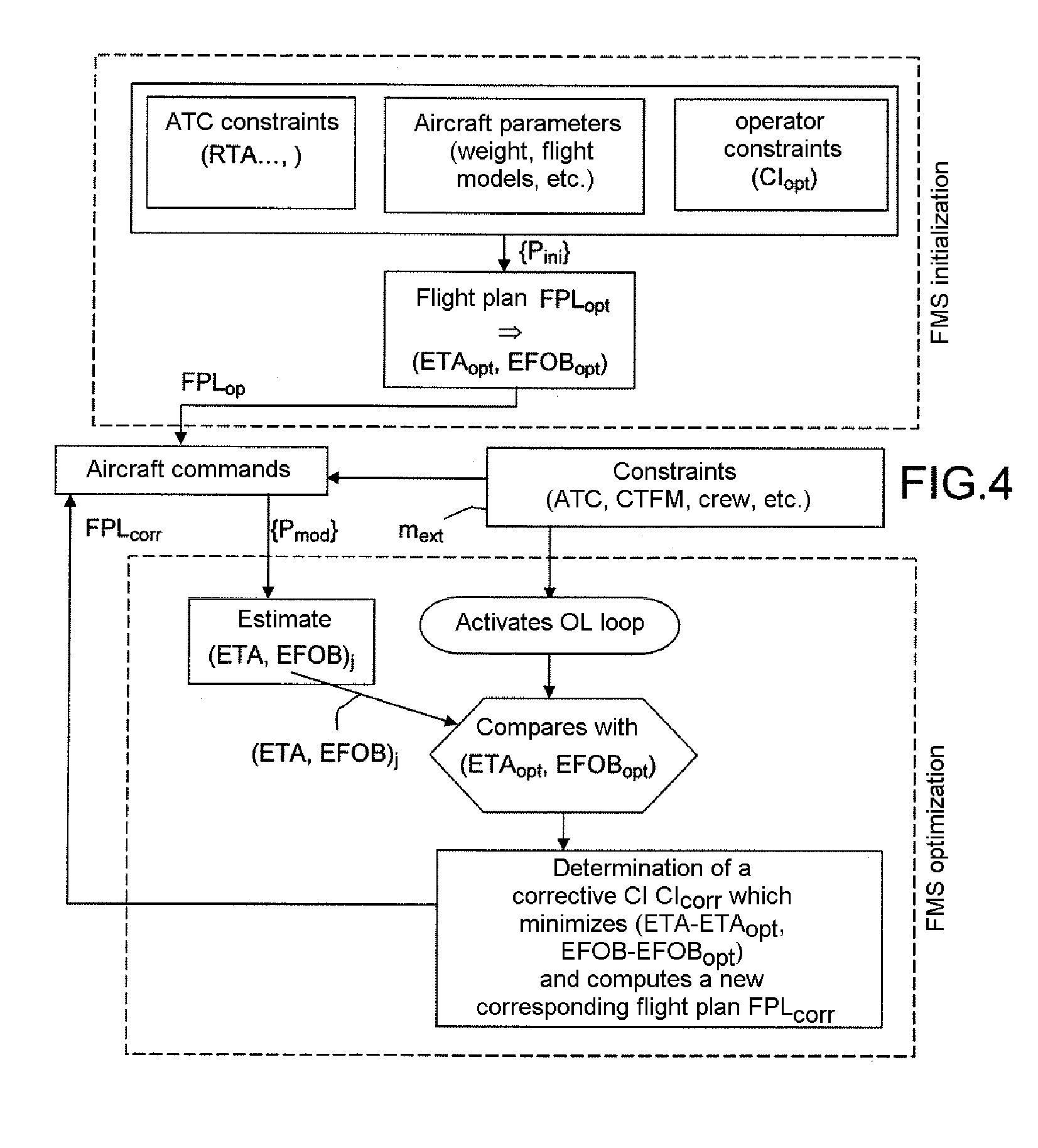
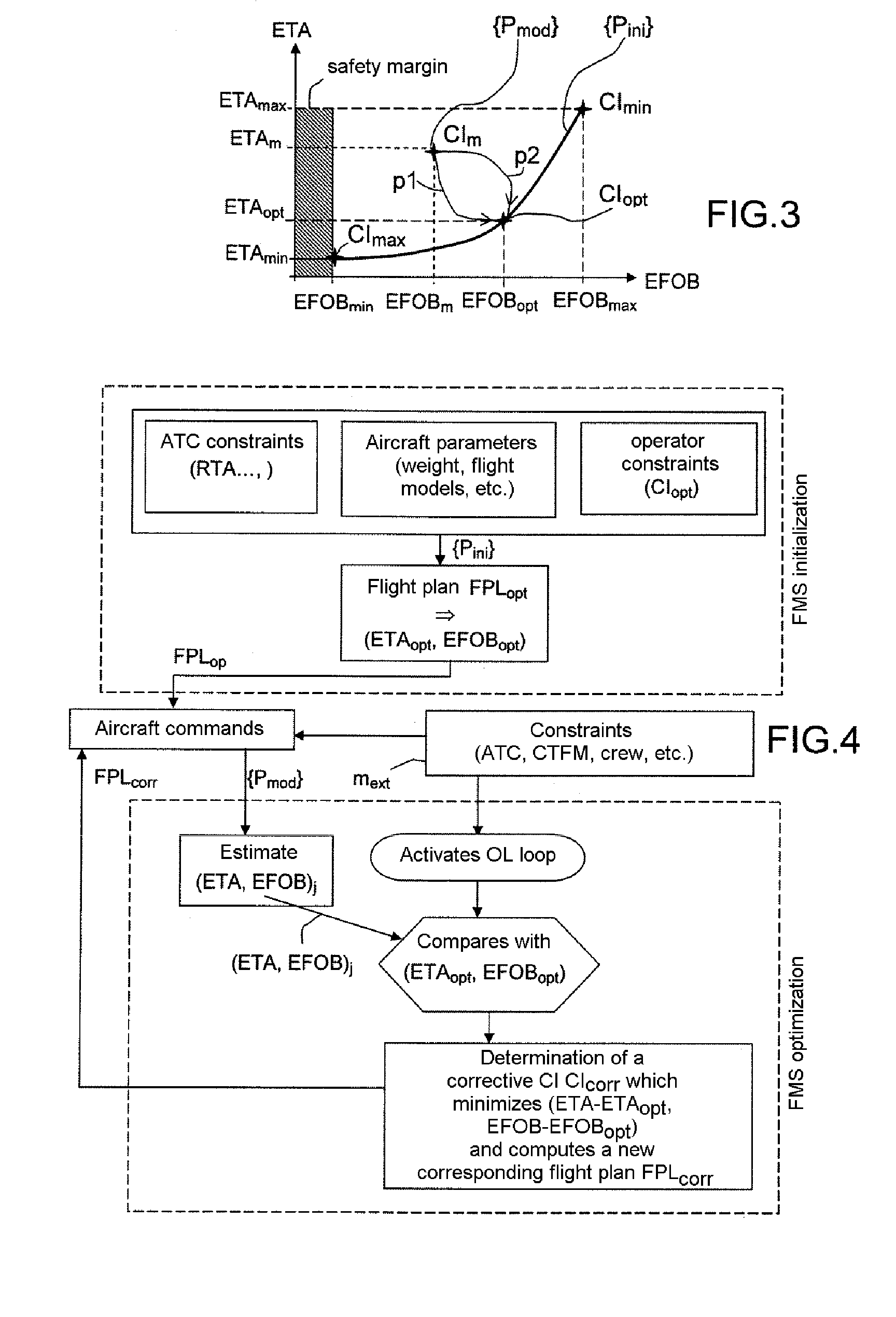
[0054]FIG. 3 illustrates a parametric curve used in the invention. This curve gives a correspondence between the values of the cost index of a given aircraft, for a given mission, and the corresponding pair (estimated time of arrival at destination ETA, quantity of fuel remaining onboard at destination).

[0055]This curve can be determined in a simple manner once the initial flight parameters {Pinit} are known that are necessary for planning the mission in question, which notably include the movement constraints, the air corridors to be used, whether or not certain devices of the aircraft are to be used (flaps, air conditioning) and navigation tools of the aircraft such as the STAR (Standard Instrument Arrival Route) and the SID (Standard Instrument Departure), the weight of the aircraft, the cruising altitude, etc.

[0056]This curve notably includes the optimal operating point marked CIopt, corresponding to the cost index determined by the operator for the given mission.

[0057]It is to ...


PUM


Abstract

A method of optimizing a flight plan of an aircraft used in a flight management system of an aircraft is disclosed. This method makes it possible to constrain the real cost index of the mission executed to the optimal cost index CIopt predetermined by the aircraft operator, by acting on objectives ETAopt and EFOBopt of values of ETA and of EFOB to be achieved. Objectives are linked to this optimal cost index, in order to make the system return from a cost index CIm to the optimal cost index CIopt, while taking account of various constraints imposed by the ATC or the CTFM. Both constraints mext influence the cost index and constraints which limit the field of possible solutions.

Description

RELATED APPLICATIONS[0001]The present application is based on, and claims priority from, French Application Number 07 03912, filed Jun. 1, 2007, the disclosure of which is hereby incorporated by reference herein in its entirety.FIELD OF THE INVENTION[0002]The present invention relates to aircraft flight management systems designated by the acronym FMS, and more particularly a method for optimizing a flight plan generated by such systems.BACKGROUND OF THE INVENTION[0003]These flight management systems FMS are well known. They make it possible to generate the flight plan of an aircraft on each mission, taking account of the parameters specific to the aircraft and to the flight conditions such as the payload, the weight of the aircraft, the quantity of fuel onboard, the temperature, the wind etc., and of the time constraints imposed by the air traffic control bodies ATC: required departure and / or arrival timeslot.[0004]The flight plan notably describes all the waypoints or positions ab...

Claims


Application Information

Patent Timeline
Patent Type & Authority Patents(United States)
IPC IPC(8): G01C23/00G06F17/00G06F19/00G06F7/00G05D3/00G05D1/00G06G7/70G06G7/76
CPCG01C21/20G05D1/0005
Inventor COULMEAU, FRANCOISDEKER, GUYGOUTELARD, HERVE
Owner THALES SA
Learn More