Battery cover assembly

a battery cover and battery technology, applied in the field of power supply system or battery system, can solve the problems of compromising connection and harming battery integrity, and achieve the effect of preventing snapping

Active Publication Date: 2011-07-21
FORD GLOBAL TECH LLC
View PDF19 Cites 22 Cited by
  • Summary
  • Abstract
  • Description
  • Claims
  • Application Information

AI Technical Summary

Benefits of technology

[0016]The width of the tab is less than the width of the recess to allow the tab to index in to the recess. The housing may be a clam-shell having first and second sections which are configured to receive the

Problems solved by technology

By forcing the bus bar to bend, the connection may be compromised and harm the integrity of the battery.
Also, it is desirable for the temperature sensors to be located

Method used


Image

  • Battery cover assembly
  • Battery cover assembly
  • Battery cover assembly

Examples


Embodiment Construction

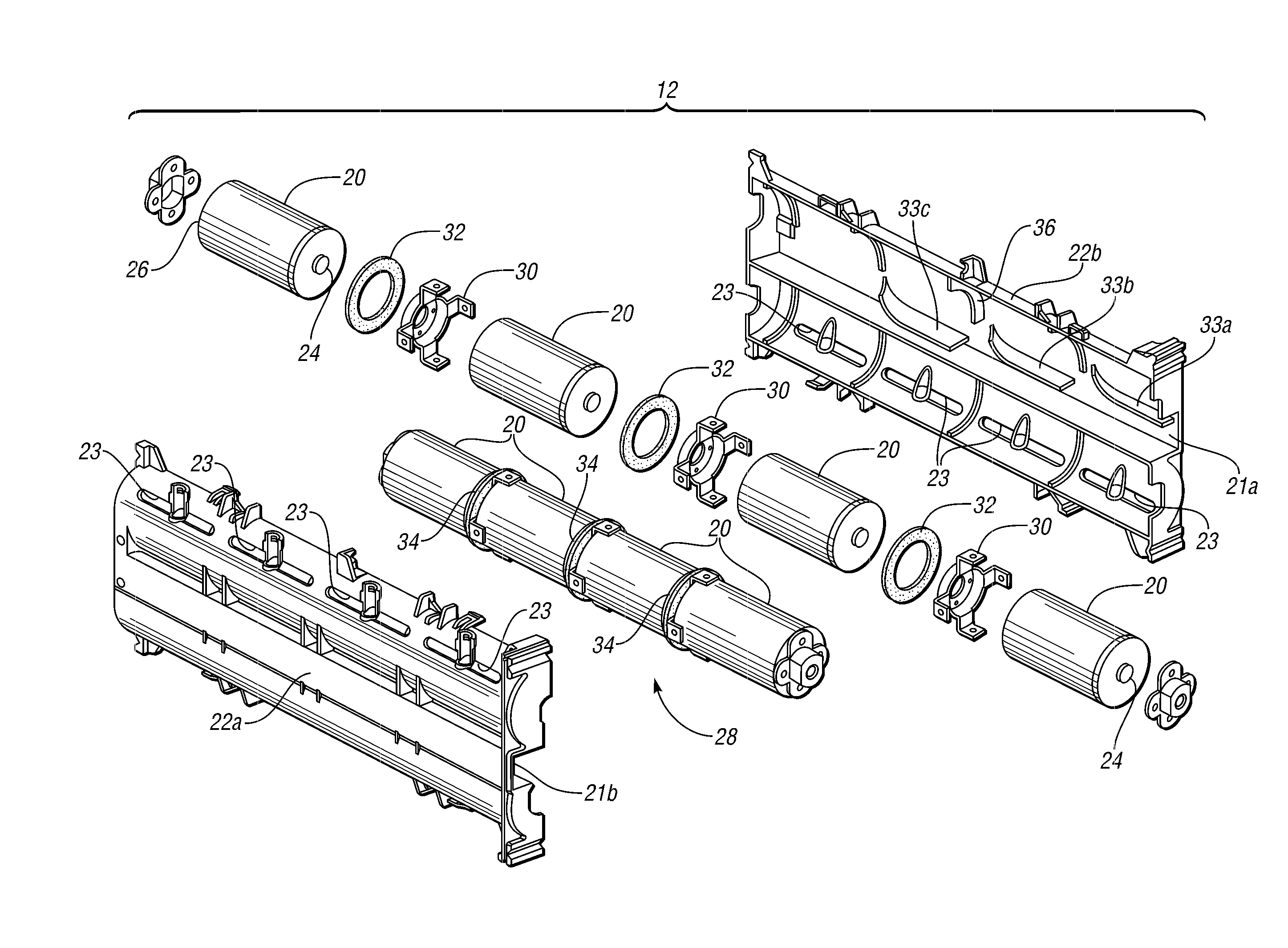
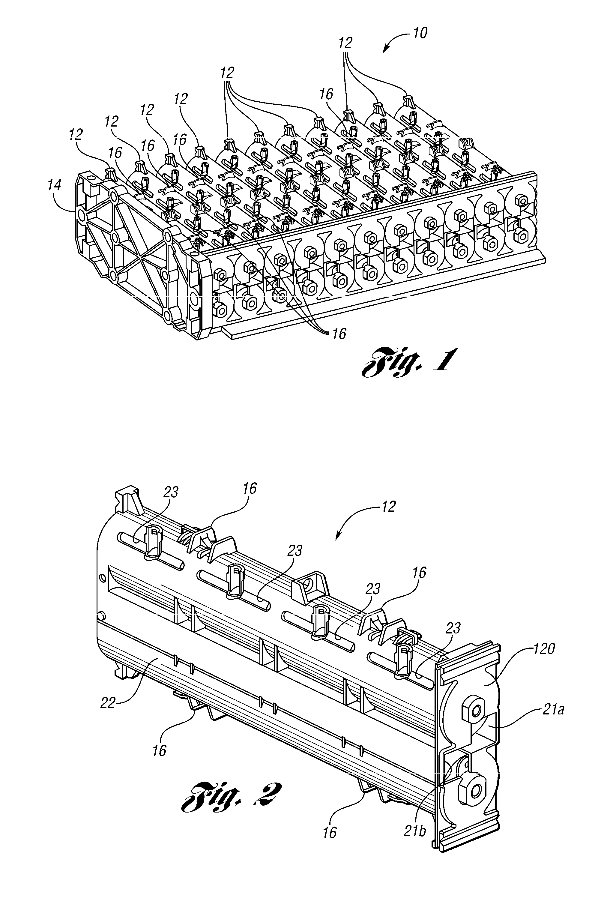
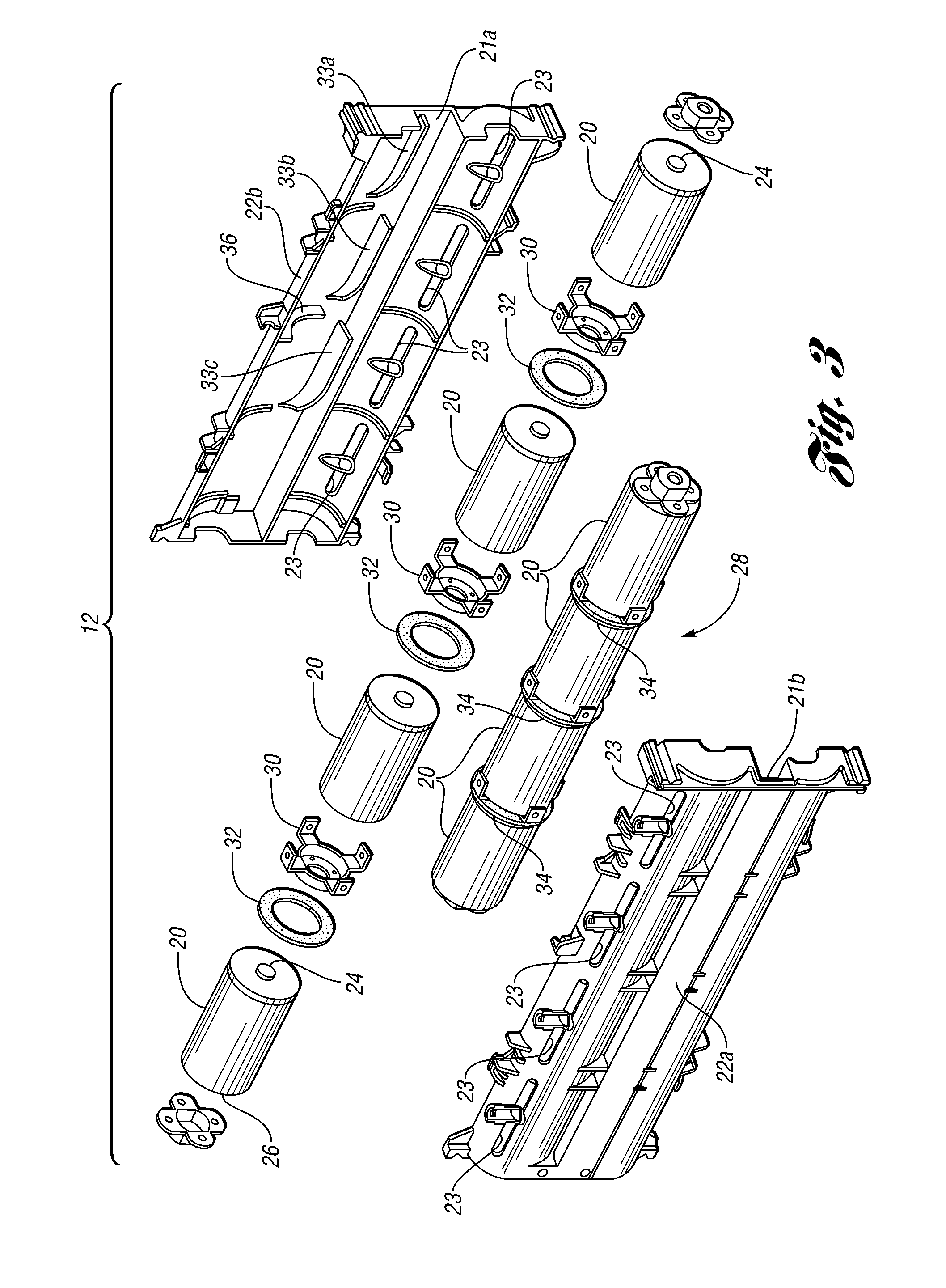
[0040]As those of ordinary skill in the art will understand, various features of the embodiments illustrated and described with reference to any one of the Figures may be combined with features illustrated in one or more other Figures to produce alternative embodiments that are not explicitly illustrated and described. The combinations of features illustrated provide representative embodiments for typical applications. However, various combinations and modifications of the features consistent with the teachings of the present disclosure may be desired for particular applications or implementations. Those of ordinary skill in the art may recognize similar applications or implementations consistent with the present disclosure, e.g., ones in which components are arranged in a slightly different order than shown in the embodiments in the Figures. Those of ordinary skill in the art will recognize that the teachings of the present disclosure may be applied to other applications or impleme...


PUM


Abstract

An end-to-end cell connection system for a battery assembly uses a conductive interconnector with an inner portion welded to an end of one cell, a standoff portion contiguous with the ring portion, tabs extending from the standoff portion, with the tabs welded to an end of another cell. By placing an insulator between the interconnector and the one cell, an electrical short is prevented in the event that a longitudinally coupled cell group is jostled. At the cell connections, there is a recess. To hold the cell group in place, the housing has a tab extending into the recess. The tab is at the center so that any dimensional variations are accommodated on each side of the tab. The interconnector also may include a receptacle for a thermistor to obtain a measure of battery assembly temperature. Diverter ribs may be provided in the housing to distribute flow to all cells.

Description

BACKGROUND[0001]1. Technical Field[0002]The present disclosure relates to a power supply system or battery system, which can be used in a hybrid electric vehicle.[0003]2. Background Art[0004]A battery for a hybrid electric vehicle may include many cells electrically connected. To attain a battery of a sufficiently high voltage, cells are electrically connected serially. Groups of several cells can be coupled longitudinally and then placed in a housing with groups arranged in parallel compartments. And, although cell groups are physically arranged in a parallel fashion, they may be electrically coupled either in series or in parallel. Groups of individual cells within a housing can be called a brick. A plurality of bricks are arranged in an array and electrically connected via bus bars to provide the desired voltage and current characteristics for the particular application. Such connected plurality of bricks forms a battery.[0005]To avoid shorts among cells within a group due to lon...

Claims


Application Information

Patent Timeline
IPC IPC(8): H01M6/42H01M50/213H01M50/262H01M50/271H01M50/503H01M50/51H01M50/516
CPCH01M2/022H01M2/1077H01M2/206H01M10/482Y10T29/49108H01M10/5004H01M10/5016H01M10/503H01M10/5073H01M10/486H01M10/625H01M10/643H01M10/6566H01M10/613Y02E60/10H01M50/107H01M50/51H01M50/213H01M50/503H01M50/516H01M50/262H01M50/271H01M50/258
Inventor MAGUIRE, PATRICK DANIEL
Owner FORD GLOBAL TECH LLC
Why Eureka
Try Eureka