Apparatus and method for imaging feet

a technology of foot and foot, applied in the field of foot and foot apparatus, can solve the problems of only providing benefits, inconvenience and potential discomfort for patients, fatiguing the clinician, etc., and achieve the effect of not affecting the soft tissue or bone structure of the foo

Active Publication Date: 2013-10-29
NORTHWEST PODIATRIC LAB
View PDF37 Cites 19 Cited by
  • Summary
  • Abstract
  • Description
  • Claims
  • Application Information

AI Technical Summary

Benefits of technology

[0014]The present invention addresses the problems cited above, and provides an apparatus for determining contours of the plantar surfaces of a patient's foot, with the foot optimally positioned and configured and without distortion of the soft tissues or bone structure of the foot.

Problems solved by technology

Although in many cases substantial benefits can be achieved using inserts and other orthotic devices constructed on the basis of one or more standardized or idealized models of feet, the characteristics of feet naturally vary from person to person, so that in general the maximum benefits can only be provided by a custom-fitted device.
Although the traditional cast-molding system described in the preceding paragraph can yield excellent results, it is by nature highly labor intensive and time-consuming in practice; furthermore, the process of applying the material to the patient's foot and allowing it to take a set while holding the foot in position requires a minimum of several minutes to complete, during which the foot must be kept essentially immobile, causing inconvenience and potential discomfort to the patient as well as being fatiguing for the clinician.
Moreover, common practice is for the molds of the patient's feet to be obtained by podiatrists and other practitioners in various locales and then sent to a specialist laboratory for actual manufacture of the orthotic devices, resulting in significant delays as well as shipping costs.
However, despite these advantages such systems have on whole failed to provide entirely satisfactory results in terms of the end product, especially by comparison to the traditional molding process.
One of the principal reasons, the inventor has found, is that in general such systems have necessarily imparted a degree of distortion to the foot during operation: For example, many prior optical scanners and imagers involve the patients standing on or otherwise placing their feet against a panel of glass or other transparent material, via which the plantar surfaces are exposed to the light source / sensor; pressing the foot against the panel causes the soft tissues of the foot to flatten and spread out in the areas of contact, so that when imaged the surface may be in a configuration that is far from optimal in terms of the function and comfort of the foot.
In addition to distortion of the soft tissues, a serious but somewhat more subtle problem relates to positioning of the bone structure of the foot.
Accurately configuring an orthotic device to meet this goal, however, requires being able to ascertain the contours of the foot with the bone structure in the correct end-point condition, specifically with the subtalar joint of the foot in what is referred to as the “neutral position” and with the midtarsal joint locked, which is generally difficult or even impossible to accomplish using prior systems such as those noted above.
The matter is greatly complicated by the fact that individual feet vary greatly in terms of overall orientation (e.g., in the amount of pronation) when the joints of the foot are in the correct condition.

Method used


Image

  • Apparatus and method for imaging feet
  • Apparatus and method for imaging feet
  • Apparatus and method for imaging feet

Examples


Embodiment Construction

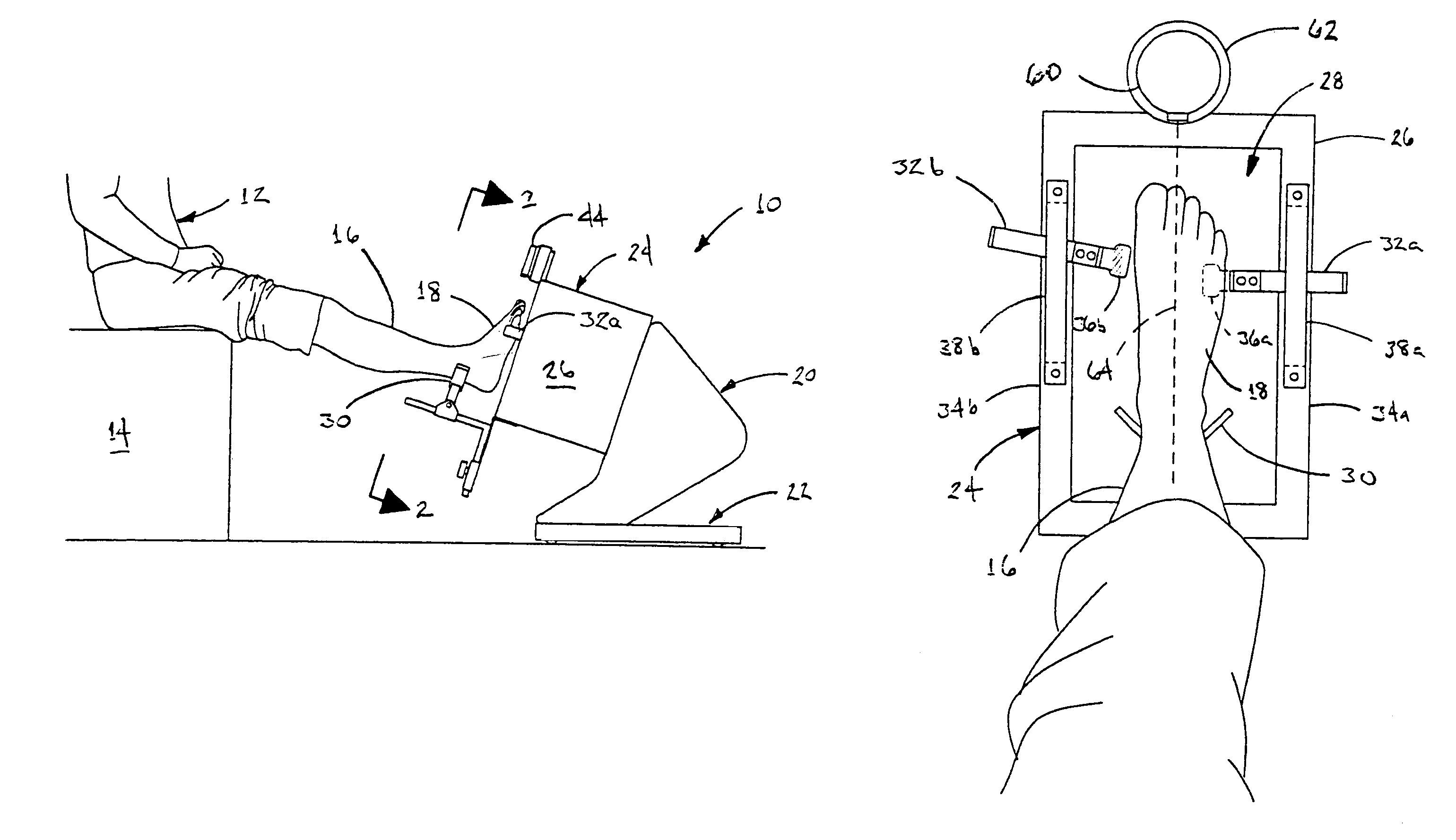
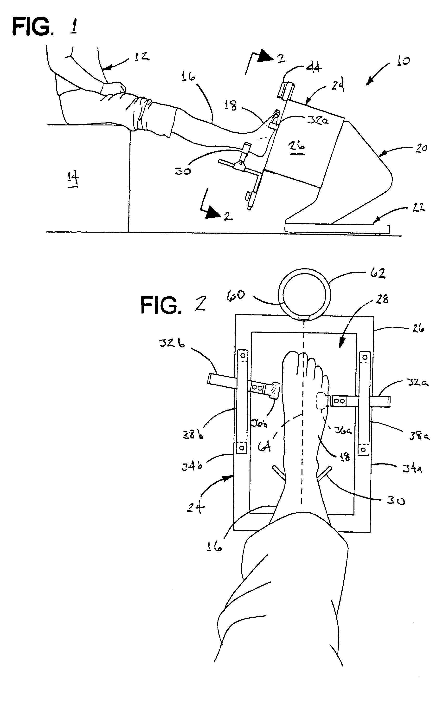
[0046]FIG. 1 shows a foot imaging apparatus 10 in accordance with a first preferred embodiment of the present invention. The apparatus is shown in use in conjunction with a patient 12 in a seated position on a chair 14 or other support, with a leg 16 and foot 18 outstretched.

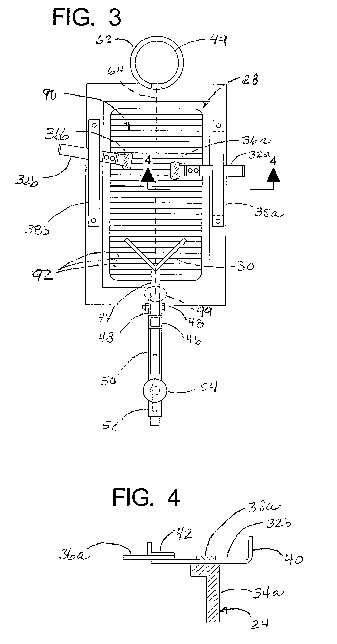
[0047]As can be seen with further reference to FIG. 1, the imaging apparatus 10 includes an optical imaging section 20 mounted on a rolling chassis section 22, and an alignment section 24 that is spaced from the imaging section 20 towards the patient's foot 18. The alignment section 24 in the illustrated embodiment includes a spacer frame 26, which in the embodiment illustrated in FIG. 6-7 is formed by a somewhat box-shaped structure, with a through passage and open ends that define an aperture 28 via which the plantar surface of the foot is exposed to the optics of the imaging section 20. A principal function of the spacer frame is to support the alignment components, as described below, such that the plantar s...


PUM


Abstract

An apparatus and method for determining contours of a patient's foot. The apparatus includes an alignment section that orientates the foot relative to an optical imaging section. The alignment section includes at least one support member located proximate a focal length of the imaging section, that engages the plantar surface substantially only in the immediate area of the fifth metatarsal head of the foot. The support generates a dorsally-directed load that locks the midtarsal joint. The alignment section further includes a heel stirrup and a laser beam or other reference line for aligning the second metatarsal head with the distal one-third of the lower leg, to place the subtalar joint in a neutral condition. The foot is thus suspended in space such that the imaging section is able to obtain an accurate measurement of the plantar surface without distortion of the soft tissues or bone structure of the foot.

Description

RELATED CASES[0001]This application claims the priority of Provisional Application No. 61 / 402,601 filed on Aug. 31, 2010.BACKGROUND[0002]a. Field of the Invention[0003]The present invention relates generally to apparatus and methods for obtaining measurements of human feet, and, more particularly, to an apparatus and method for obtaining measurements of the contours of human feet with the feet held in a preferred physical configuration, for use in the manufacture of orthotic devices or for other purposes.[0004]b. Related Art[0005]Obtaining accurate measurements of the human foot, and more particularly an accurate determination of its shape and contours, is desirable for many purposes. Perhaps the most basic reason is for the sizing and fitting of shoes, but beyond this are more particular purposes such as for constructing specialized shoe inserts and other orthotic devices. In general terms, the purpose of such orthotic devices is to optimize functions of the foot and / or to correct ...

Claims


Application Information

Patent Timeline
Patent Type & Authority Patents(United States)
IPC IPC(8): A61B5/107
CPCA61B5/0082A61B5/1077A61B5/6829G01B11/24A61B5/1074A61B5/107A61B5/103A43D1/02A43D1/025
Inventor SMITH, CHRISTOPHER E.
Owner NORTHWEST PODIATRIC LAB
Why Eureka
Try Eureka