Profile measuring instrument

a technology of measuring instruments and profiles, applied in the direction of instruments, mechanical measuring arrangements, using mechanical means, etc., can solve the problems that the model of the patent literature 2 cannot be directly transformed into a transfer function, and the abbreviation error cannot be appropriately compensated

Active Publication Date: 2013-10-29
MITUTOYO CORP
View PDF23 Cites 8 Cited by
  • Summary
  • Abstract
  • Description
  • Claims
  • Application Information

AI Technical Summary

Benefits of technology

[0015]An object of the invention is to provide a profile measuring instrument that can appropriately compensate the Abbe's error.
[0017]According to the above arrangement, since the compensation-amount calculating unit calculates at least one of the translation-compensation amount and the rotation-compensation amount based on the rotation frequency of the scanning movement of the probe, even when the model of the Abbe's error has to be represented by a high-order transfer function, the Abbe's error can be appropriately compensated.
[0025]According to the above arrangement, since the rotation frequency calculating unit calculates the rotation frequency based on the command value, the Abbe's error of the autonomous scanning movement can be appropriately compensated.
[0027]According to the above arrangement, since the rotation frequency calculating unit calculates the rotation frequency based on the radius determined by the path setting unit, the Abbe's error of the design-value scanning movement can be appropriately compensated.
[0034]According to the above arrangement, even when the translation-compensation amount and the rotation-compensation amount become discontinuous, with the use of segmented polynomial equations segmented at the discontinuous point or a spline function, the coefficients with less error can be determined in accordance with the rotation frequency, so that the Abbe's error can be appropriately compensated.

Problems solved by technology

However, since the CMM disclosed in the Patent Literature 2 compensates the Abbe's error based on the function of the probe position Ps and the acceleration a, the Abbe's error cannot be appropriately compensated when the model of the Abbe's error has to be expressed by a high-order transfer function.
Further, the model of the Patent Literature 2 cannot be directly transformed into a transfer function.

Method used


Image

  • Profile measuring instrument
  • Profile measuring instrument
  • Profile measuring instrument

Examples


first exemplary embodiment

[0049]A first exemplary embodiment of the invention will be described below with reference to the attached drawings.

Schematic Arrangement of Coordinate Measuring Machine

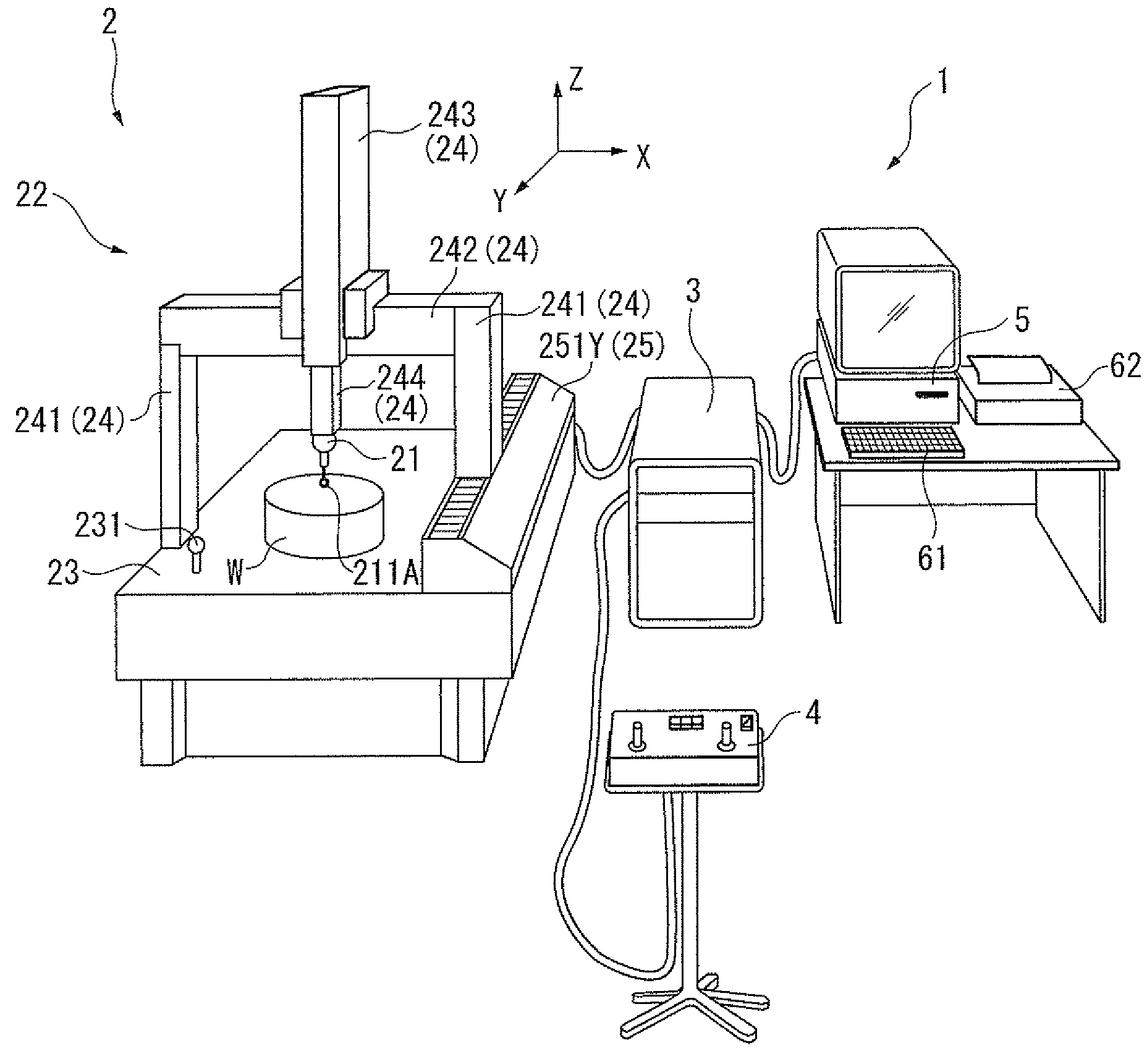
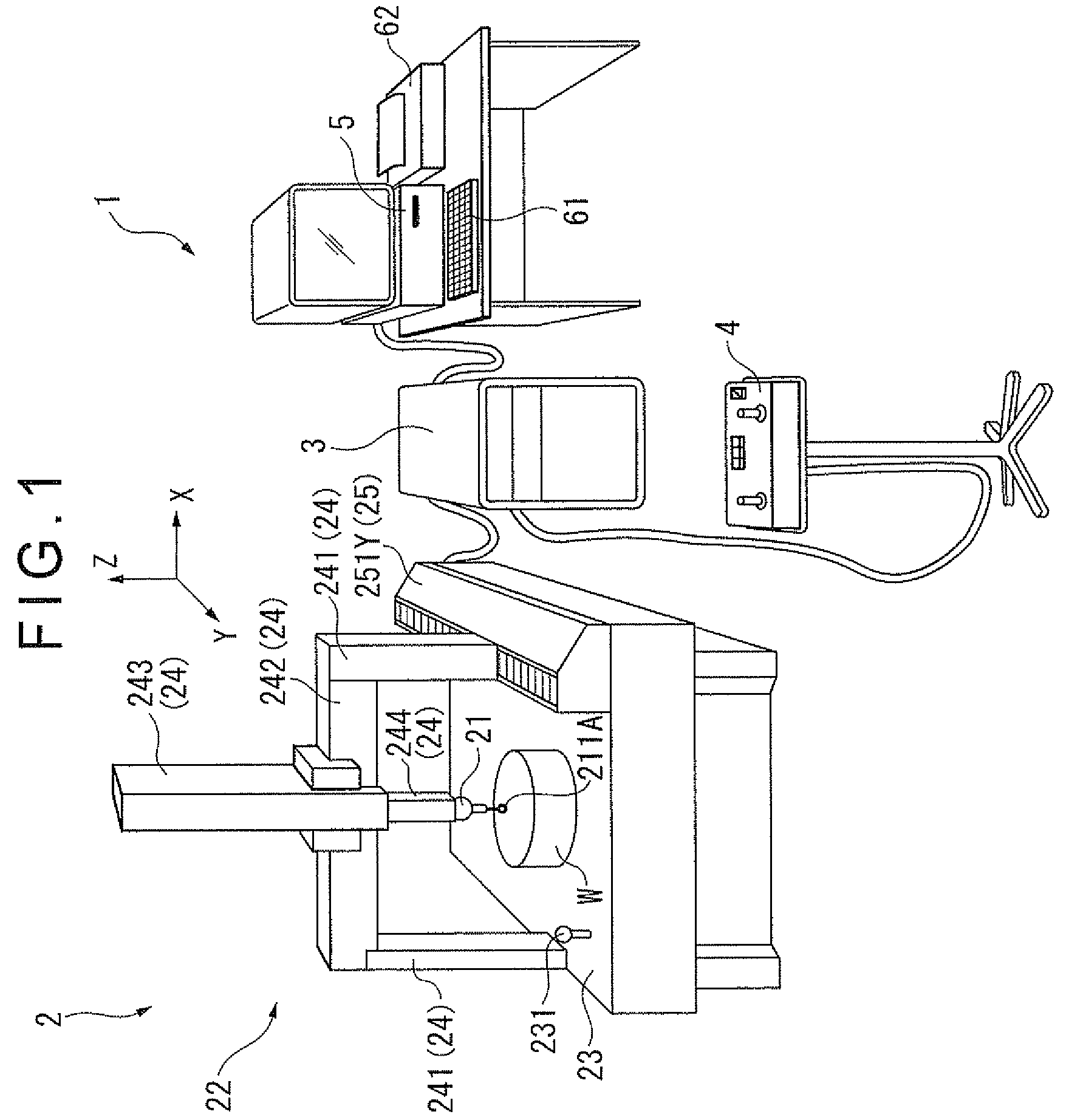
[0050]FIG. 1 is a schematic illustration of an entire coordinate measuring machine according to the first exemplary embodiment of the invention. Incidentally, upper direction in FIG. 1 will be referred to as +Z-axis direction and two axes orthogonal to the Z-axis will be described as X-axis and Y-axis respectively, which also applies in the rest of the drawings.

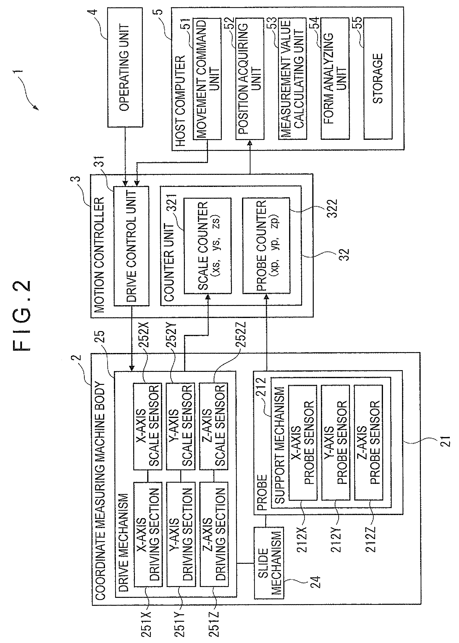
[0051]As shown in FIG. 1, the coordinate measuring machine 1 (profile measuring instrument) includes: a coordinate measuring machine body 2; a motion controller 3 for performing a drive control over the coordinate measuring machine body 2; an operating unit 4 that provides a command to the motion controller 3 via an operation lever or the like to manually operate the coordinate measuring machine body 2; a host computer 5 that provides a predetermined command t...

second exemplary embodiment

[0121]A second exemplary embodiment of the invention will be described below with reference to the attached drawings. Incidentally, the components that have been described above will be denoted by the same reference numeral and the description thereof will be omitted in the following description.

[0122]FIG. 9 is a block diagram showing a schematic arrangement of a coordinate measuring machine 1A according to the second exemplary embodiment of the invention.

[0123]In the first exemplary embodiment, the coordinate measuring machine 1 includes the host computer 5, and the host computer 5 includes the movement command unit 51 and the measurement value calculating unit 53. In contrast, the coordinate measuring machine 1A according to the second exemplary embodiment includes a host computer 5A, and the host computer 5A includes a path setting unit 56, a movement command unit 51A and a measurement value calculating unit 53A.

[0124]The path setting unit 56 designates the path of the probe 21 b...


PUM


Abstract

A coordinate measuring machine includes a probe having a measurement unit, a movement mechanism for moving the probe and a host computer for controlling the movement mechanism. The host computer includes: a compensation-amount calculating unit for calculating a compensation amount for compensating an error in the position of the measurement unit caused by the movement of the probe; and a compensator for compensating the error in the position of the measurement unit based on the compensation amount calculated by the compensation-amount calculating unit. The compensation-amount calculating unit calculates a translation-compensation amount for compensating a translation error of the probe and a rotation-compensation amount for compensating a rotation error of the probe based on a rotation frequency of the movement of the probe.

Description

[0001]The entire disclosure of Japanese Patent Application No. 2010-165731 filed Jul. 23, 2010 is expressly incorporated by reference herein.BACKGROUND OF THE INVENTION[0002]1. Field of the Invention[0003]The present invention relates to a profile measuring instrument.[0004]2. Description of Related Art[0005]A known profile measuring instrument includes: a probe having a measurement unit for measuring an object; a movement mechanism for moving the probe; and a controller for controlling the movement mechanism, the measurement unit being moved along a surface of the object to measure a profile of the object (see, for instance, Patent Literature 1: JP-A-55-154408 and Patent Literature 2: JP-A-07-324928).[0006]A coordinate measuring machine according to the Patent Literature 1 uses acceleration of respective driven components or acceleration obtained by a drive motor in order to compensate measurement errors caused by a deflection of a movement mechanism on account of inertial force du...

Claims


Application Information

Patent Timeline
Patent Type & Authority Patents(United States)
IPC IPC(8): G01B5/008G01B7/008
CPCG01B21/045
Inventor OGIHARA, MOTONORINAKAGAWA, HIDEYUKI
Owner MITUTOYO CORP
Why Eureka
Try Eureka