Roller transmission and gearing mechanism

a transmission mechanism and roller technology, applied in the direction of gearing, gearing elements, hoisting equipment, etc., can solve the problems of not being able to achieve all the benefits, not being able to achieve the effects of reducing distance, facilitating entry and discharge of roller means, and reducing distan

Active Publication Date: 2013-10-29
BOGAR PAL
View PDF10 Cites 7 Cited by
  • Summary
  • Abstract
  • Description
  • Claims
  • Application Information

AI Technical Summary

Benefits of technology

[0010]It is a primary objective of the present invention to provide a novel transmission and gearing mechanism, that is free of most of the aforementioned drawbacks and limitations of the existing transmission and gearing systems, has a higher power-transmission efficiency, requires smaller space and can transmit higher torques.
[0033]An alternative solution for providing a well-functioning return path is when a gradually reduced distance is provided between adjacent roller guide tracks close to the roller guide track terminating limit surfaces, and a gradually increased distance is provided between adjacent roller guide tracks close to the roller guide track starting limit surfaces.
[0034]In a further way of providing a smooth transition to and from the return path the roller guide tracks are gradually enlarged at the starting and ending portions of the tracks when approaching the limit surfaces, whereby the forces acting on the roller means are reduced and both the entry and discharge of the roller means are facilitated.
[0035]The roller transmission and gearing mechanism according to the present invention attains all objectives set and provides a new solution to transmission and gering tasks, wherein direct transmission can be provided in a small space between any relative locations of the driving and driven bodies, the force and torque that can be transmitted can be increased by increasing the engagement factor between the driving and driven bodies. The elimination of sliding movement reduces frictional energy losses and increases power transmission efficiency. The advantages listed are far from being exhaustive.

Problems solved by technology

Worm gears for example are notorious for their particularly low power transmission efficiency.
They dissipate significant amounts of energy due to large frictional energy losses as a result of extensive sliding between their contact surfaces.
These designs, however, have not managed to bring on all the benefits that could have been expected from the application of rolling balls because the conditions for pure rolling motion for the balls were not met.
In the absence of these conditions the balls were forced to slide extensively along their tracks resulting in sub-optimal transmission efficiency due to significant frictional energy losses.
The fact, however, that ball-screws of the mentioned coaxial type can only be applied for transforming rotational movement to a linear displacement along a path parallel to the axis of rotation, makes them inapplicable in providing movements of higher degrees of freedom such as those along two- or three-dimensional paths; and due to such limitations this particular gearing system has not become more generally applicable and widespread.
One of the disadvantages is that the engagement factor i.e. the number of teeth in simultaneous contact at any given time is relatively small and cannot be increased significantly.
This means that the mechanical load is concentrated on a small number of engaging teeth and therefore the maximum transmissible power is relatively low compared to the size and space used, and difficult to increase significantly.
Besides the limitations for the maximum transmissible power, there is not much room for manoeuvring to vary the distance and the angle between the driving and driven shafts either.
This, on one hand, increases the size of the set-up and, on the other hand, introduces extra frictional energy losses.
One of the most important disadvantages of the toothed wheels is frictional energy losses arising from the fact that the connecting teeth of the wheels slide on each other most of the time of their engagement.
This causes a significant reduction in the power transmission efficiency even if proper lubrication is applied.

Method used


Image

  • Roller transmission and gearing mechanism
  • Roller transmission and gearing mechanism
  • Roller transmission and gearing mechanism

Examples


Embodiment Construction

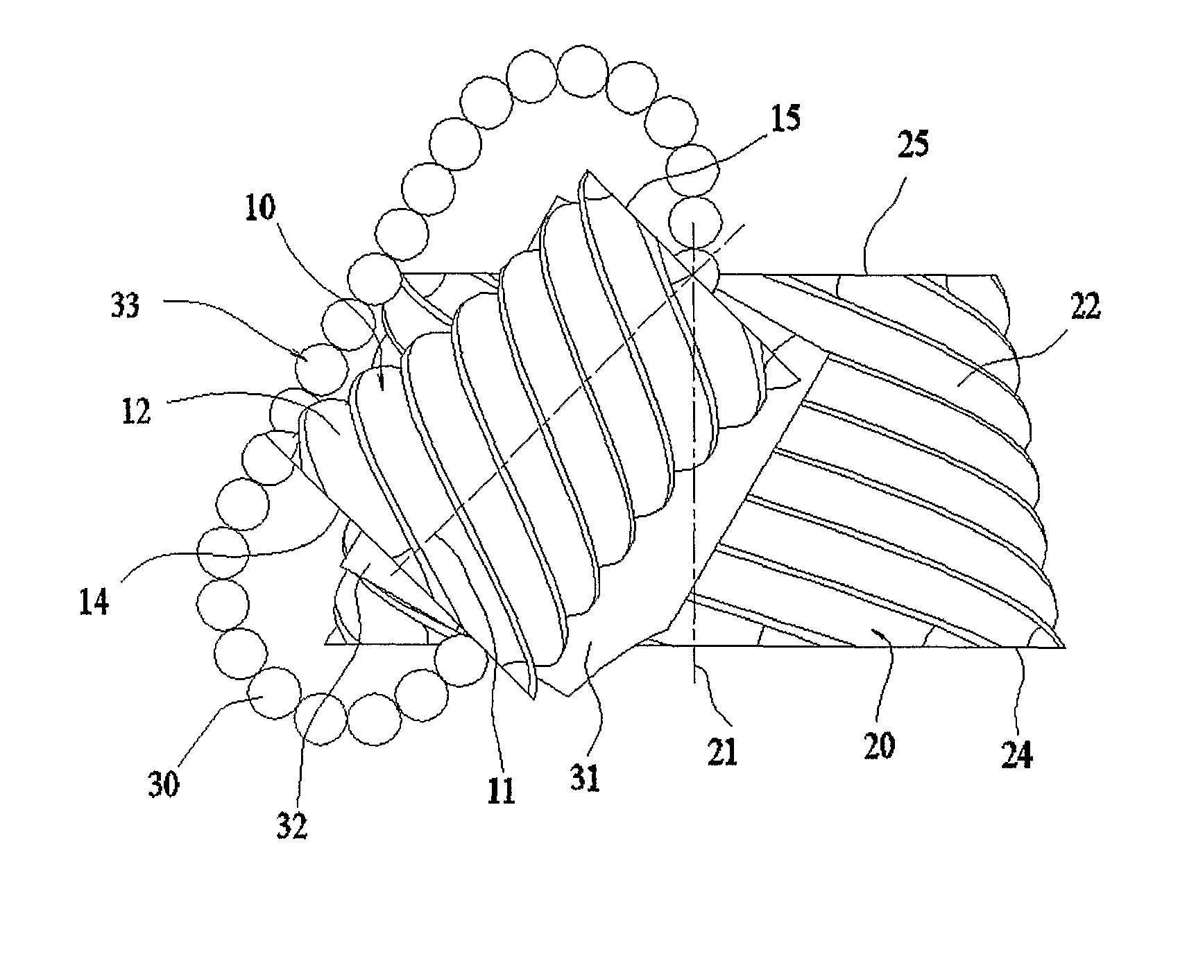
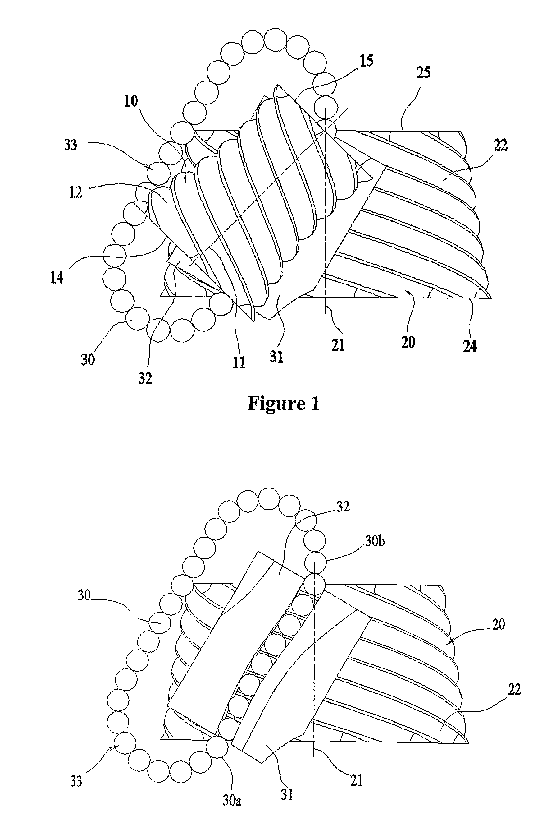
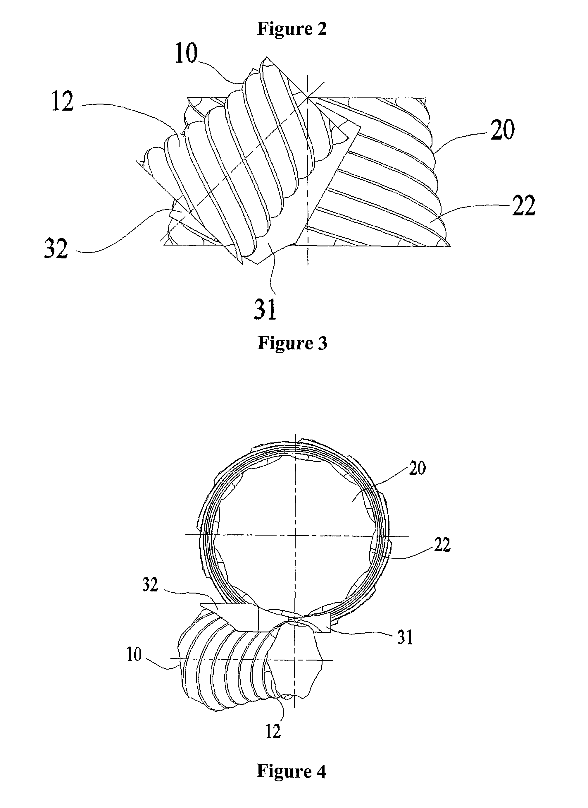
[0074]In order to show the main parts and the main features of the roller transmission and gearing mechanism introduced in the present invention first an example for the basic design will be shown where the two bodies are two rotationally symmetric wheels set-up with their rotational axes forming skew lines with respect to each other and including an angle. FIG. 1 shows a schematic drawing of this design including first wheel 10 and second wheel 20 and their respective rotational axes 11 and 21. In the present description, “wheels” mean rotationally symmetric bodies that can rotate around their axes of symmetry but are fixed along their axial directions. Each body has either an inner or an outer rotationally symmetric surface centred at the rotational axis of the body onto which the roller guide tracks are developed. These surfaces will be referred to as track surfaces. The track surfaces are bounded by two separated limit surfaces that are typically but not always planes normal to ...


PUM


Abstract

A roller transmission and gearing mechanism with a driving body, one or more rollers, and a driven body coupled to the driven body via the rollers. The bodies define at least one pair of respective roller guide tracks thereon. The guide tracks start and terminate at respective pairs of limit surfaces. The rollers contact the guide tracks along rolling curves, and distances between points of the rolling curve on the driving body and the respective rolling curve on the driven body are different such that: for all contacting point-pairs on the rolling curves, the respective tangential planes are parallel to each other; the velocities of the contacting pairs of points are identical but have opposite signs; in the contacting points, the action lines of forces intersect the central axes of the rollers; and the lengths of the rolling curves of the driving and driven bodies are equal.

Description

BACKGROUND OF THE INVENTION[0001]1. Field of the Invention[0002]The invention relates to a roller transmission and gearing mechanism that comprises a driving body, roller means having respective centres or central axes, and a driven body, wherein the driving body is coupled to the driven body by means of the roller means, the driving and driven body are guided for movement having a single degree of freedom, the driving and driven bodies both define respective roller guide tracks thereon, the tracks contact the roller means and determine the relative movement of the roller means with respect to the associated body, the roller means contact the roller guide tracks along respective rolling curves, the roller guide tracks start and terminate on the driving and driven bodies at respective pairs of limit surfaces, the roller means move along their associated roller guide tracks, wherein the roles of the driving and driven bodies can be interchanged.[0003]2. Description of Related Art[0004...

Claims


Application Information

Patent Timeline
Patent Type & Authority Patents(United States)
IPC IPC(8): F16H25/06
CPCF16H1/163Y10T74/19698Y10T74/19953Y10T74/19749F16H1/16F16H25/22
Inventor BOGAR, ISTVAN
Owner BOGAR PAL
Why Eureka
Try Eureka