Blow molding machine for containers and mandrel holder

a technology for blow molding machines and containers, which is applied in the direction of conveyor control devices, conveyor parts, mechanical conveyors, etc., can solve the problems of troublesome handling, non-positive support of positive locking, and inconvenient mouth types, etc., and achieves short strokes, low effort and cost, and low force expenditure

Inactive Publication Date: 2013-10-29
KRONES AG
View PDF18 Cites 10 Cited by
  • Summary
  • Abstract
  • Description
  • Claims
  • Application Information

AI Technical Summary

Benefits of technology

[0004]Aspects underlying the disclosure are to provide a blow molding machine of the type mentioned in the beginning as well as a mandrel holder for a pre-forming mandrel which are operator-friendly and permit extraordinarily short change times.
[0005]By the functional separation of the two aspects, on the one hand of reliably generating the high retention force for the pre-forming mandrel by the clamping mechanism, and on the other hand of actuating the releasing element for releasing the clamping mechanism as smooth-running as possible and in an ergonomically advantageous manner, the handling of the coupling is very operator-friendly and the coupling can be very quickly engaged and released, respectively. That is to say that, for releasing the clamping mechanism, the releasing element can be moved essentially independently of the retention force easily and over only a small stroke until the pre-forming mandrel can be removed or falls out automatically, while the clamping mechanism alone takes care of the high retention force when the releasing element is not being actuated.
[0006]Advantageously, the coupling of the mandrel holder is a ball joint lock which is constructively simple, fail-safe and easy to actuate, nevertheless generates the high retention force required for the pre-forming mandrel, and only the releasing element is moved relative to the mandrel holder to release the ball joint lock. No force has to be applied on the pre-forming mandrel. The action of the releasing element on the ball joint lock can be designed such that the same can be readily and quickly released despite the high retention force with relatively little releasing force and a small stroke. The ball joint lock has the further advantage of permitting the insertion of the pre-forming mandrel by simply fitting it in without having to use the releasing element for this operation, too. This does not exclude that a ball joint lock is still used which requires the actuation of the releasing element also for inserting the pre-forming mandrel.

Problems solved by technology

That is to say that the pre-forming mandrel very precisely fits into the mouth and is therefore not suited for different mouth types.
In addition, a spring is provided which non-positively supports the positive locking.
Handling is troublesome, takes quite a long time and requires considerable skills.
As often several hundreds of mandrel holders are arranged in the conveyor path, exchange lasts inappropriately long.

Method used


Image

  • Blow molding machine for containers and mandrel holder
  • Blow molding machine for containers and mandrel holder
  • Blow molding machine for containers and mandrel holder

Examples


Embodiment Construction

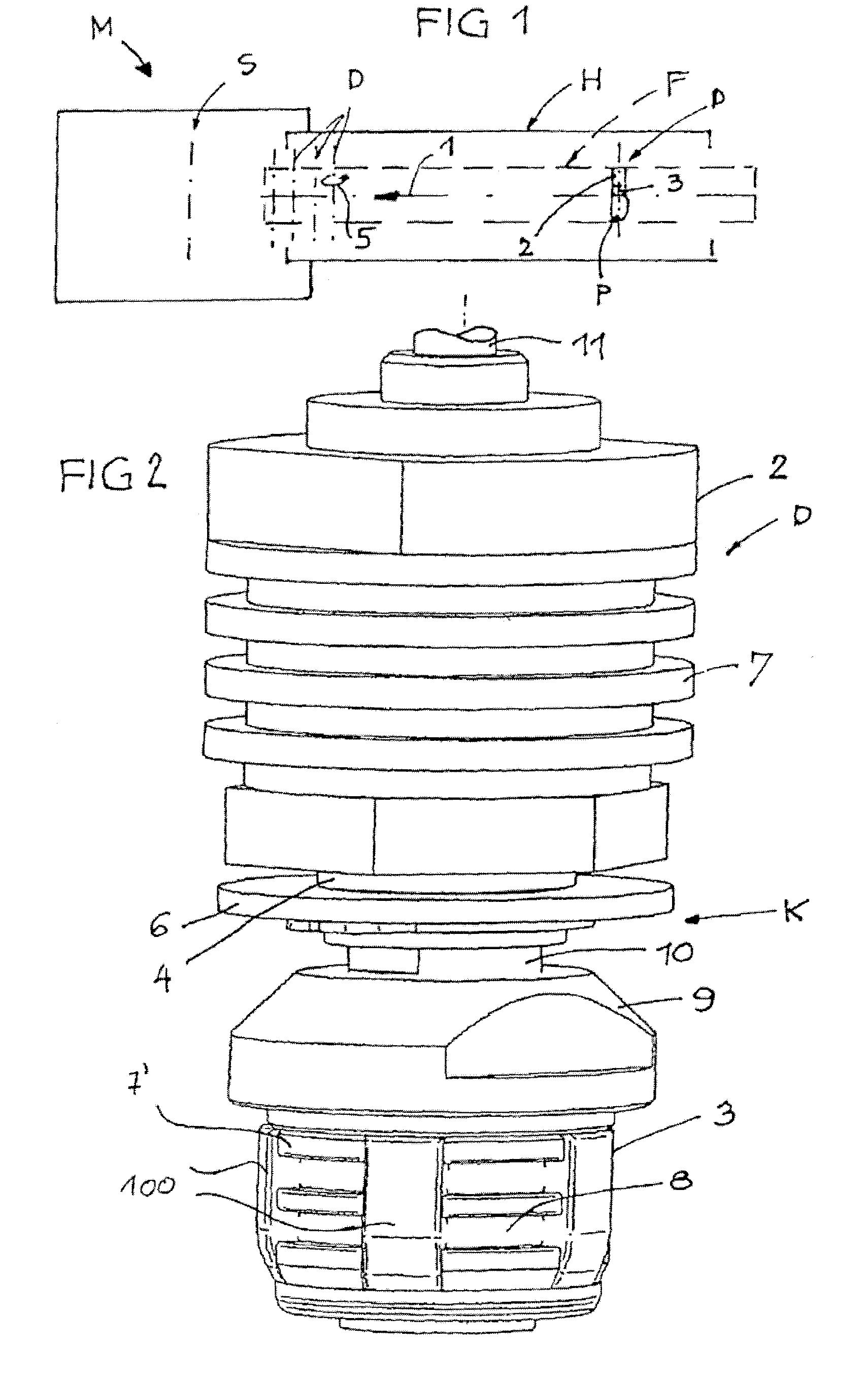
[0030]FIG. 1 schematically illustrates a blow molding machine M for containers, for example a stretch-blow molding machine for plastic bottles. A blowing station S with a non-depicted blow molding star is connected to a conveyor path F which at least in sections runs through a heating device H for preforms P to be heated or to be treated thermally. The conveyor path F in operation moves in the conveying direction 1 and contains a plurality of mandrel devices D placed close to each other, each consisting of a mandrel holder 2 transportable in the conveyor path F and mounted to be suspended in this case, and a pre-forming mandrel 3 attached thereto in an exchangeable manner, onto which one preform P each can be placed. The mandrel devices D are possibly rotated about their axes in the sense of rotation 5 in operation.

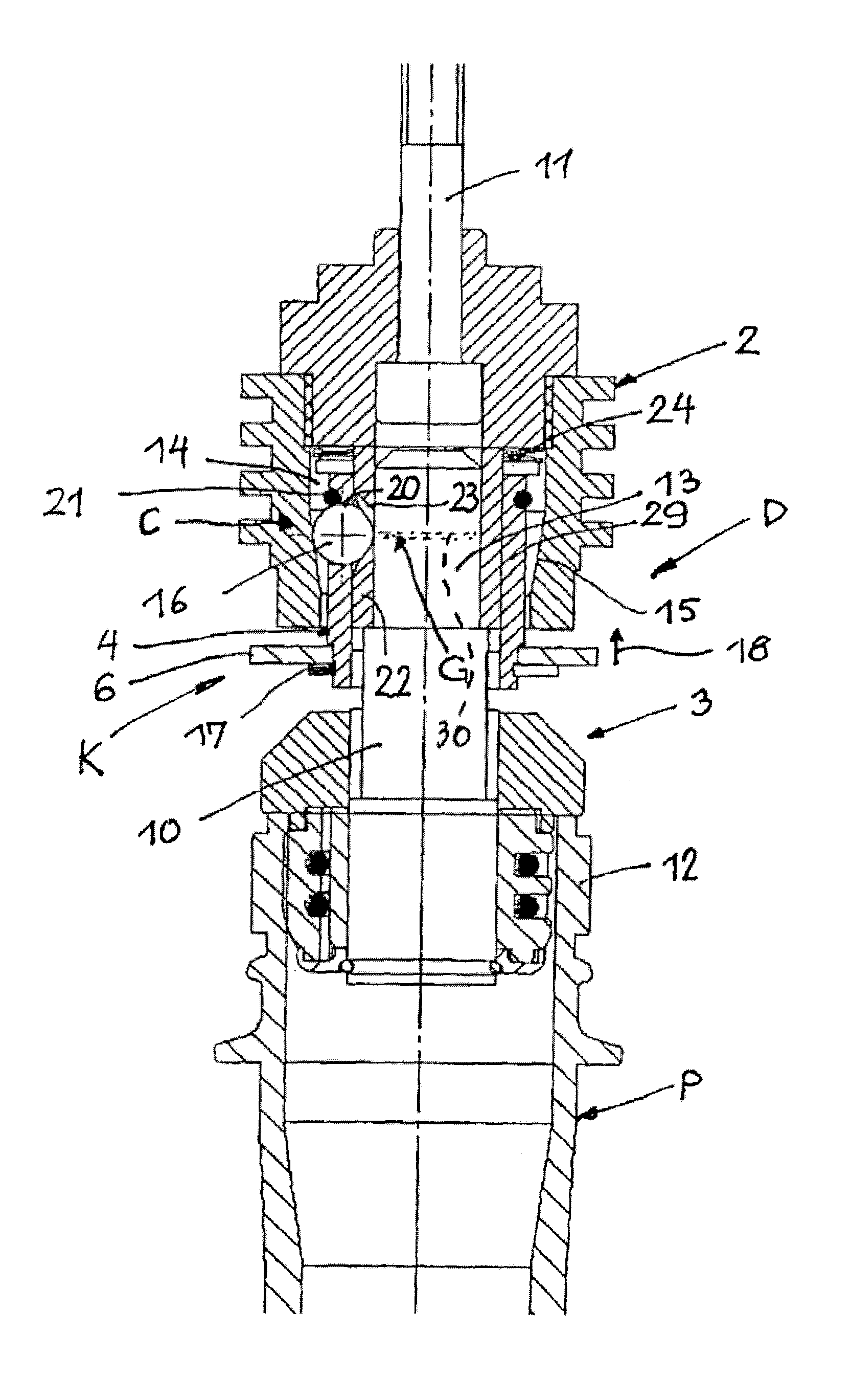
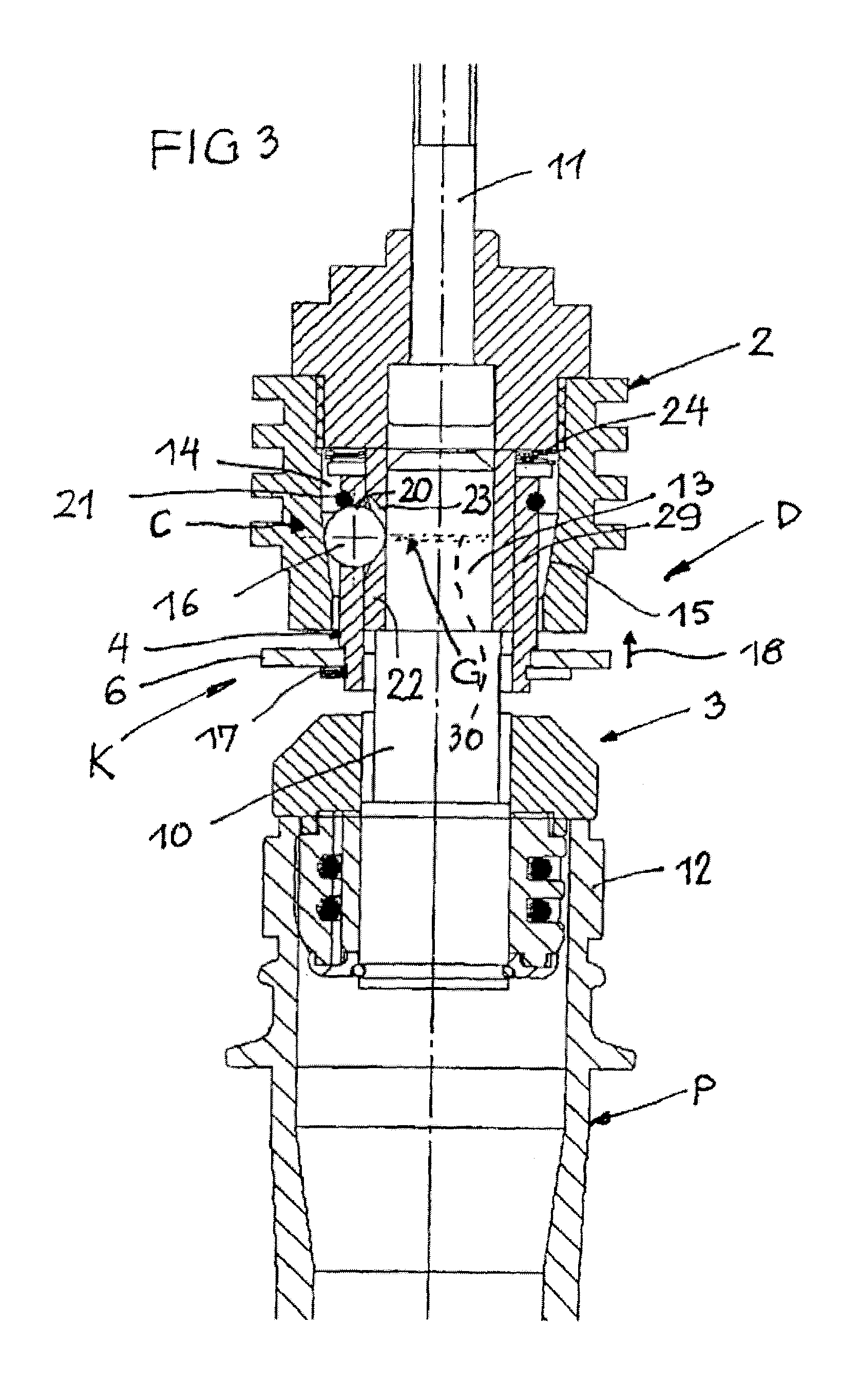
[0031]According to FIGS. 2 and 3, the pre-forming mandrel 3 is mounted at the mandrel holder 2 mounted via a shaft 11 in an exchangeable manner by means of a releasable c...


PUM

PropertyMeasurementUnit
thermal stressaaaaaaaaaa
timeaaaaaaaaaa
retention forceaaaaaaaaaa

Abstract

A blow molding machine for containers, having a conveyor path carrying a mandrel holder and pre-forming mandrels attached to the mandrel holders in an exchangeable manner by means of removable couplings, wherein each coupling has a mandrel clamping mechanism and a releasing element accessible form outside that can be adjusted at least relative to the mandrel holder for releasing the clamping mechanism. In the mandrel holder, particularly for use in a blow molding machine, the mandrel clamping mechanism is designed with a ball joint lock, and the ball joint lock can be released by means of a releasing element in order to exchange a performing mandrel.

Description

CROSS-REFERENCE TO RELATED APPLICATION[0001]The present application claims the benefit of priority of International Patent Application No. PCT / EP2008 / 006282, filed Jul. 20, 2008, which application claims priority of European Patent Application No. 102007037400.5, filed Aug. 8, 2007. The entire text of the priority application is incorporated herein by reference in its entirety.FIELD OF THE DISCLOSURE[0002]The disclosure relates to a blow molding machine as well as to a mandrel holder for use in container molding apparatus.BACKGROUND[0003]In stretch-blow molding machines for plastic bottles, prefabricated preforms are conveyed in a conveyor path through a heating station before they are processed in the blowing station. Each preform is already embodied with a mouth which at least essentially corresponds to the mouth of the finished bottle, and it is held in the conveyor path at this mouth by an inserted pre-forming wing mandrel. The pre-forming mandrel is fixed at the mandrel holder ...

Claims


Application Information

Patent Timeline
Patent Type & Authority Patents(United States)
IPC IPC(8): B29C49/42B65G17/20B65G17/32B29C49/48B65G47/86
CPCB29C49/4205B65G47/842B65G47/847B29C2049/4856B29C2049/5893B29C49/42081B29C49/42085
Inventor SCHONBERGER, WOLFGANG
Owner KRONES AG
Why Eureka
Try Eureka