Mobile cart base with traction wheel

a mobile cart and base technology, applied in the field of carts, can solve the problems of poor difficult steering of the cart, and difficulty in steering the cart, so as to improve the maneuverability of the cart, the effect of easy steering and stopping

Active Publication Date: 2013-10-29
JACO
View PDF39 Cites 8 Cited by
  • Summary
  • Abstract
  • Description
  • Claims
  • Application Information

AI Technical Summary

Benefits of technology

[0007]The invention provides a multi-wheeled base for a mobile cart. The base may include one or more swiveling, optionally locking, caster wheels and one or more non-swiveling traction wheels to improve the maneuverability of the cart by making it easier to steer and stop. The traction wheels may be manually-engaged traction wheels, which in one non-limiting example may be operated by a cam and lever. The traction wheels may also be automatically-engaged traction wheels operated by a motor and a threaded shaft, activated by a motion-sensitive sensor or by an on / off electrical switch or button.

Problems solved by technology

The overall weight of some mobile carts, particularly those equipped with electronic equipment and power supplies, may be an ergonomic issue.
With an average weight exceeding 100 pounds, pushing a mobile cart can be tiring and cumbersome, especially for smaller users.
In the past, mobile carts have been equipped with four swivel casters or wheels, which permit the user to maneuver the cart around corners, or push it out of the way if necessary, but makes the cart difficult to steer.
In particular, the momentum of the cart may be a problem if the cart is moved quickly, as the cart may become difficult to stop or turn.
In addition, the carts are difficult to push in a straight line, as the four swivel casters may cause the cart to move slightly from side to side as it pushed, especially if the floors are uneven.
This is not ideal, however, because it is still difficult to turn tight corners, and nearly impossible to pivot in place.

Method used


Image

  • Mobile cart base with traction wheel
  • Mobile cart base with traction wheel
  • Mobile cart base with traction wheel

Examples


Embodiment Construction

[0041]I. Mobile Cart Base

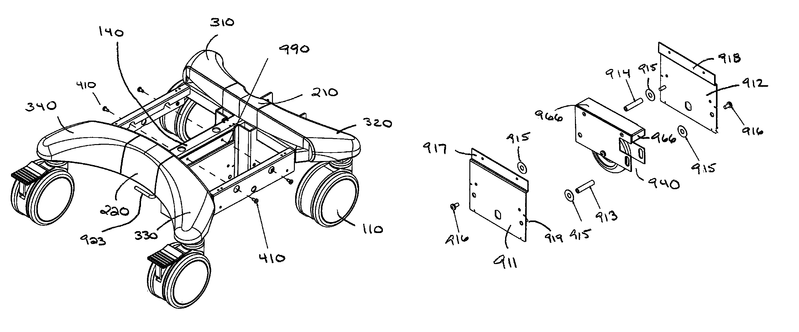
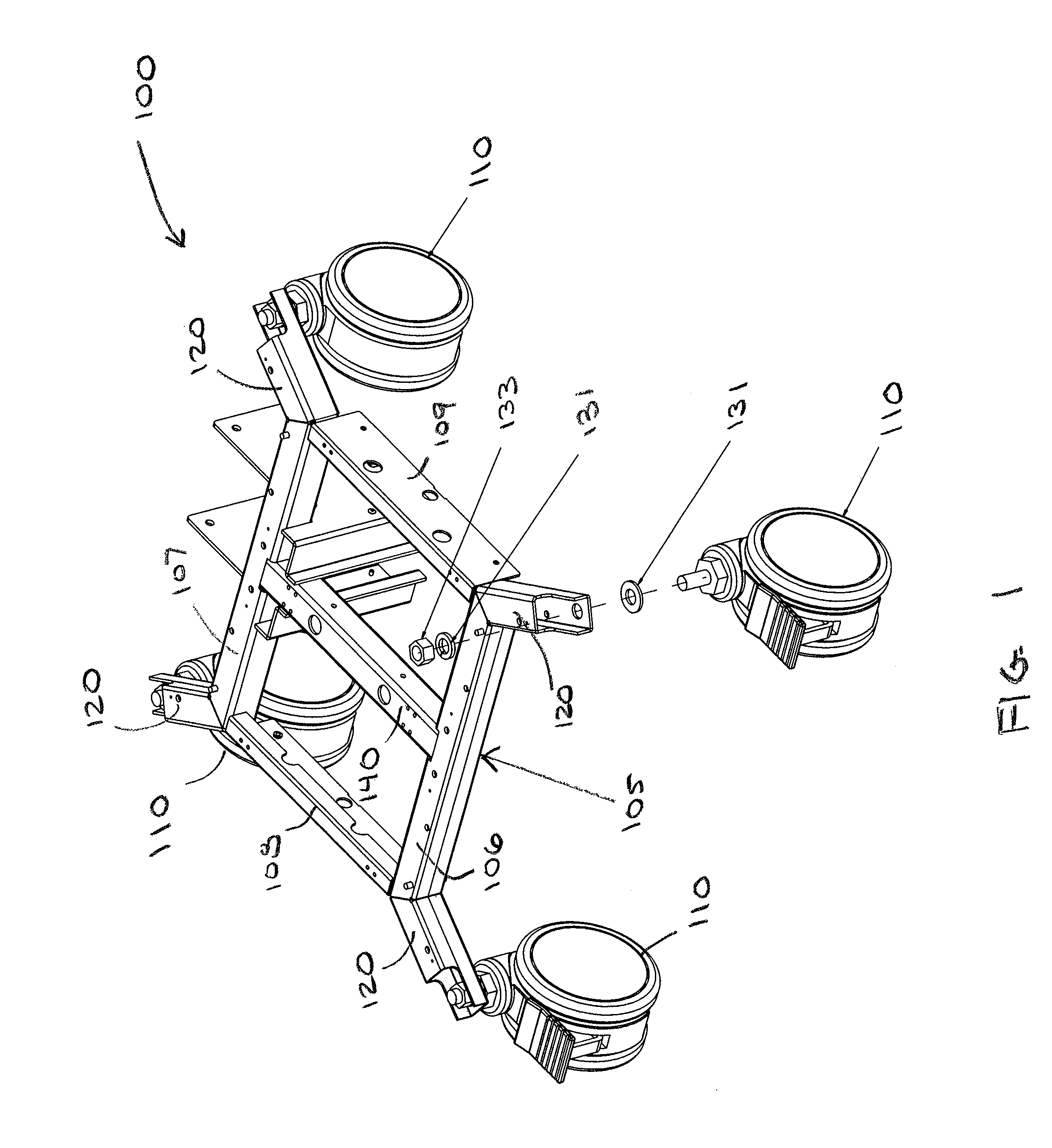
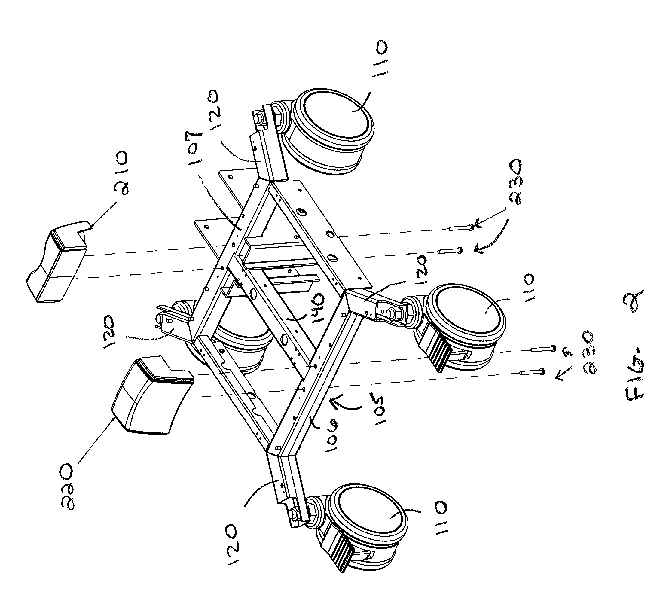
[0042]With reference to FIGS. 1 through 8, in a preferred embodiment, mobile cart base 800 comprises a rolling base section 100 that includes a generally rectangular base frame 105 and four omni-directional, optionally locking swiveling casters or wheels 110. In alternate embodiments, mobile cart base 800 may include a generally elliptical base frame, or a base frame comprising three, four or more sides, and may have two, three or more swiveling wheels.

[0043]As shown in FIG. 1, base frame 105 comprises a front frame member 106, a rear frame member 107, two opposing side frame members, left side member 108 and right side member 109, and center frame member 140. In a preferred embodiment, base frame 105 includes four protruding legs 120, one protruding leg located proximate each corner of the base frame 105. Base frame 105 is preferably constructed of metal, although other materials, suitable for accommodating the weight of the mobile cart, are within the scop...


PUM


Abstract

A multi-wheeled base for a mobile cart includes one or more swiveling, optionally locking, caster wheels and one or more non-swiveling traction wheels to improve the maneuverability of the cart by making it easier to steer and stop. The traction wheels may be manually-engaged traction wheels, which may be operated by a cam and lever. The traction wheels may also be automatically-engaged traction wheels operated by a motor and a threaded shaft, and activated by a motion-sensitive sensor or by an on / off electrical switch or button. The traction wheels are preferably in contact with the floor when the mobile cart is moving, and raised above the surface of the floor when the cart is stationary.

Description

CROSS-REFERENCE TO RELATED APPLICATION[0001]This application claims priority to U.S. Provisional Patent Application Ser. No. 61 / 308,965, entitled “MOBILE CART BASE WITH TRACTION WHEEL,” filed on Feb. 28, 2010, and is a continuation-in-part and claims priority to co-pending U.S. patent application Ser. No. 12 / 418,338, entitled “MOBILE CART,” filed on Apr. 3, 2009, which itself claims priority to U.S. Provisional Patent Application Ser. No. 61 / 074,170, entitled “BEDSIDE MEDICATION DELIVERY CART,” filed on Jun. 20, 2008. The entire contents of all three priority applications are expressly incorporated by reference herein.FIELD OF THE INVENTION[0002]The invention relates generally to the field of carts, and particularly to mobile carts with multi-wheeled bases.BACKGROUND OF THE INVENTION[0003]Mobile carts are employed in many industries, and may be used to carry a computer, monitor, display, or other electronic equipment; to provide a work surface, such as for a computer keyboard and mo...

Claims


Application Information

Patent Timeline
Patent Type & Authority Patents(United States)
IPC IPC(8): B62B3/00
CPCA61G12/001B62B3/10B62B5/0026A47B2200/0023B62B2202/56B62B2301/08B62B2301/20A61G2203/36
Inventor ROSSINI, ALFRED P.HALIO, LEONARDSILVERMAN, JEFFREY M.MALONEY, DAVIDLEITER, DAVIDBAGLEY, THOMAS
Owner JACO
Why Eureka
Try Eureka