

Organic light emitting device having cathode including a magnesium-calcium layer and method for fabricating the same
a light emitting device and magnesium-calcium technology, which is applied in the direction of discharge tube/lamp details, discharge tube luminescnet screens, transportation and packaging, etc., can solve the problems of poor electron injection characteristics of magnesium-silver alloy cathode compared to magnesium cathode, and the inability to form stable organic light emitting devices. , to achieve the effect of improving electron injection characteristics
- Summary
- Abstract
- Description
- Claims
- Application Information
AI Technical Summary
Benefits of technology
Problems solved by technology
Method used
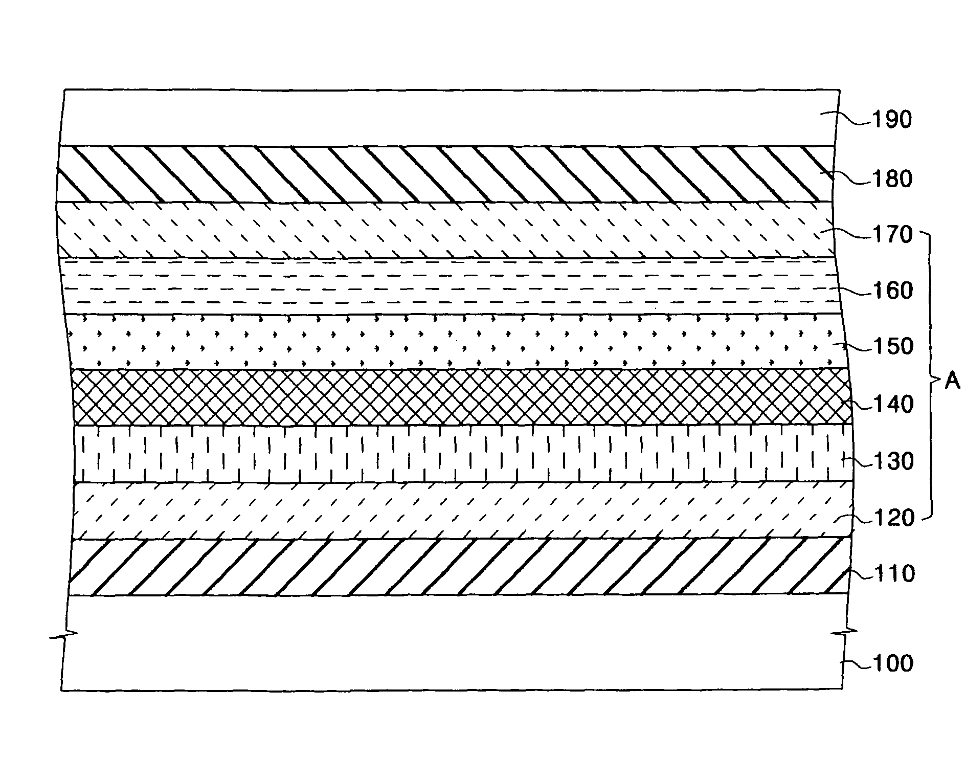
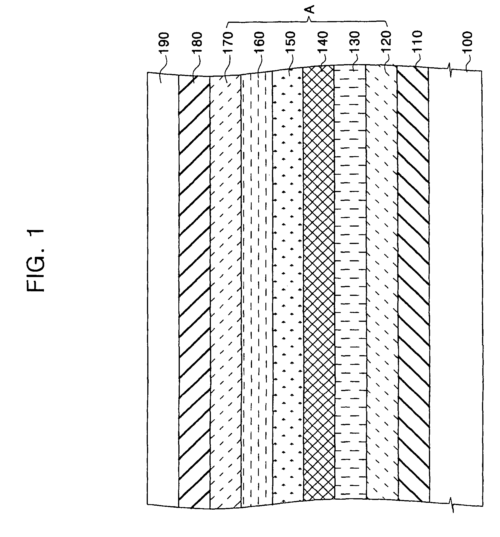
Image

Examples
example 1
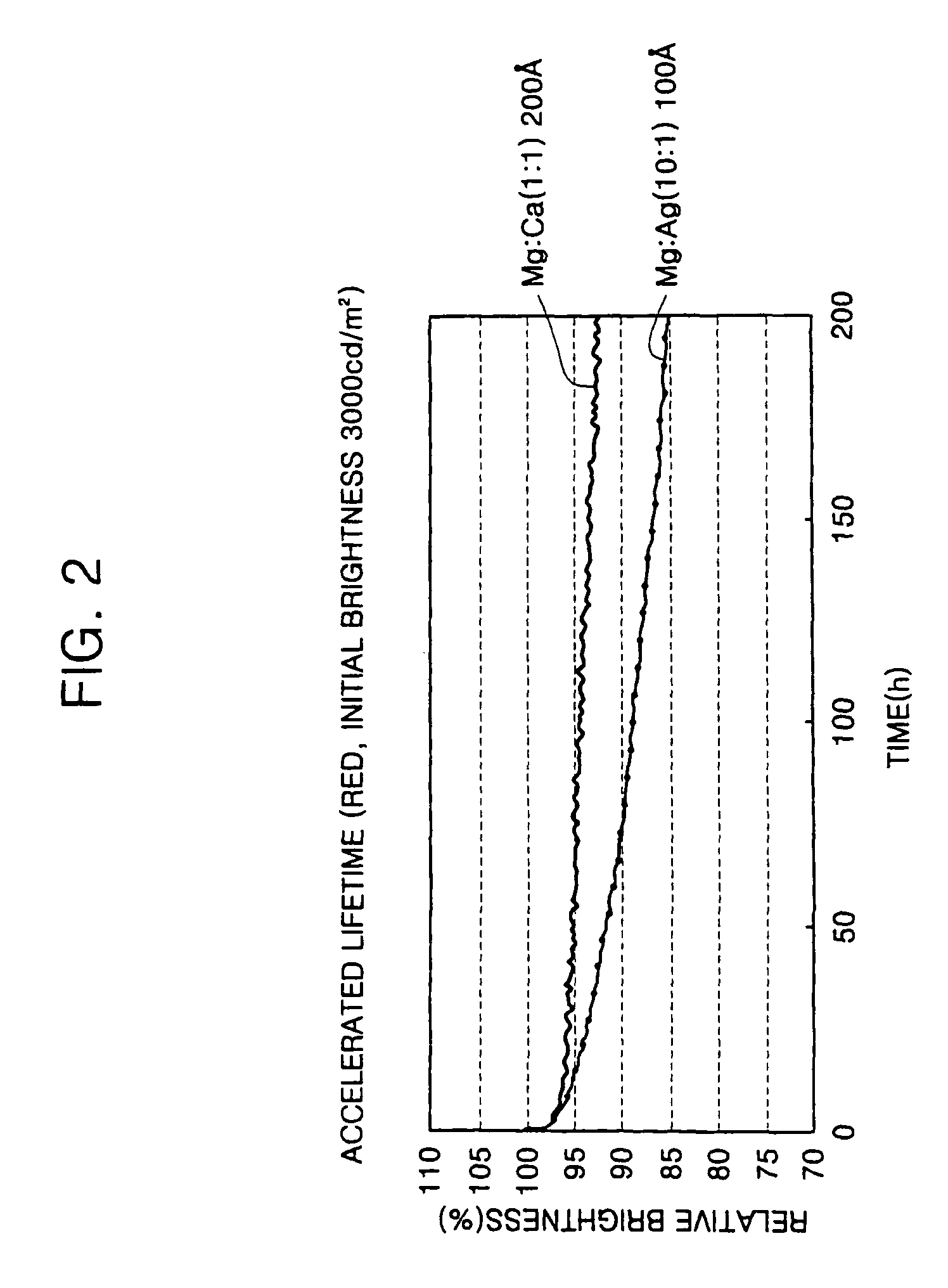
[0044](1) Fabrication of a Red Organic Light Emitting Device
[0045]An anode having an area of 2 mm×2 mm was formed on a substrate comprising ITO, and was ultrasonically cleaned and UV-O3 treated. 4,4′,4″-Tris(N,N-diphenyl-amino)-triphenylamine (TDATA) was vacuum deposited on the UV-O3 treated anode to a thickness of about 300 Å to form a hole injection layer. α-NPB(N,N′-Bis(naphthalene-1-yl)-N,N′-bis(phenyl)benzidine) was vacuum deposited on the hole injection layer to a thickness of about 300 Å to form a hole transport layer. CBP 100 part and PQ3Ir 14 part were co-deposited on the hole transport layer to form a 400 Å thick red emission layer. Balq3 was deposited on the emission layer to a thickness of about 50 Å, and Alq3 was vacuum deposited thereon to a thickness of about 250 Å to form an electron transport layer. Mg and Ca were co-deposited on the electron transport layer to form 200 Å thick Mg—Ca layer with an atomic ratio of 1:1, thereby forming a cathode. As a result, a red or...
example 2
[0060](1) Fabrication of a Green Organic Light Emitting Device
[0061]An anode having an area of 2 mm×2 mm was formed on a substrate comprising ITO, and was ultrasonically cleaned and UV-O3 treated. 4,4′,4″-Tris(N,N-diphenyl-amino)-triphenylamine (TDATA) was vacuum deposited on the UV-O3 treated anode to a thickness of about 200 Å to form a hole injection layer. α-NPB(N,N′-Bis(naphthalene-1-yl)-N,N′-bis(phenyl)benzidine) was vacuum deposited on the hole injection layer to a thickness of about 50 Å to form a hole transport layer. CBP 100 part and Ir(ppy)3 6 part were co-deposited on the hole transport layer to form a 400 Å thick green emission layer. Balq3 was deposited on the emission layer to a thickness of about 50 Å, and Alq3 was vacuum deposited thereon to a thickness of about 250 Å to form an electron transport layer. Mg and Ca were co-deposited on the electron transport layer to form 200 Å thick Mg—Ca layer with an atomic ratio of 1:1, thereby forming a cathode. As a result, a g...
example 3
[0081](1) Fabrication of a Blue Organic Light Emitting Device
[0082]An anode having an area of 2 mm×2 mm was formed on a substrate comprising ITO, and was ultrasonically cleaned and UV-O3 treated. 4,4′,4″-Tris(N,N-diphenyl-amino)-triphenylamine (TDATA) was vacuum deposited on the UV-O3 treated anode to a thickness of about 200 Å to form a hole injection layer. α-NPB(N,N′-Bis(naphthalene-1-yl)-N,N′-bis(phenyl)benzidine) was vacuum deposited on the hole injection layer to a thickness of about 50 Å to form a hole transport layer. DPVBi was vacuum deposited on the hole transport layer to form a 150 Å thick blue emission layer. Alq3 was vacuum deposited on the emission layer to a thickness of about 250 Å, to form an electron transport layer. Mg and Ca were co-deposited on the electron transport layer to form a 160 Å thick Mg—Ca layer with an atomic ratio of 1:1, thereby forming a cathode. As a result, a blue organic light emitting device was formed.
[0083](2) Measurement of Driving Voltage...
PUM
 Abstract
Description
Claims
Application Information