Voltage limiter and protection of a photovoltaic module

a photovoltaic module and voltage limiter technology, applied in the field of electromechanical devices, can solve the problems of difficult upgrade, limiting the flexibility of photovoltaic installations, and combining converters and rows of modules

Active Publication Date: 2013-10-29
COMMISSARIAT A LENERGIE ATOMIQUE ET AUX ENERGIES ALTERNATIVES
View PDF21 Cites 143 Cited by
  • Summary
  • Abstract
  • Description
  • Claims
  • Application Information

AI Technical Summary

Problems solved by technology

A problem posed by the known devices is the combination of converters and of rows of modules.
This voltage range has a significant impact on the design of the converter and so finally on the cost.
All these constraints thus considerably limit the flexibility in producing photovoltaic installations by imposing the size of the modules, their numbers and the characteristics of the converters.
Finally, an installation having been completed, it is very difficult to upgrade it by gradually adding modules (during development of a budget for example).
The installation has to be complete from the start and upgrades cannot be gradual.
Therefore a problem is posed, which is to be able to combine and adapt modules more easily.
These high voltages and currents at the outputs of the photovoltaic field are dangerous, and without any actual possibility for the user of interrupting the generator.
The connection and disconnection of modules and converters therefore have to be very often carried out during operation, with a significant risk, which is that of generating an electric arc, destructive for the electric connections, and dangerous for the user.
This arc is all the more dangerous since it is generated by a direct current, without any natural passage through zero.
Usual protections (circuit breakers and fuses) do not detect these electric arcs and are therefore not effective.
On the other hand, they do not properly provide protection against short circuits and overloads, because the short circuit currents provided by the photovoltaic fields are very close to the rated currents (factor of about 1.2).
Finally, switches, circuit breakers and fuses have much difficulty in interrupting direct currents.
Although the connections of the photovoltaic modules with each other and with the converters, are made with special sealed connectors affording good protection to the user against direct contacts, a problem of protection of the user is then posed during connections and disconnections of the modules.

Method used


Image

  • Voltage limiter and protection of a photovoltaic module
  • Voltage limiter and protection of a photovoltaic module
  • Voltage limiter and protection of a photovoltaic module

Examples


first embodiment

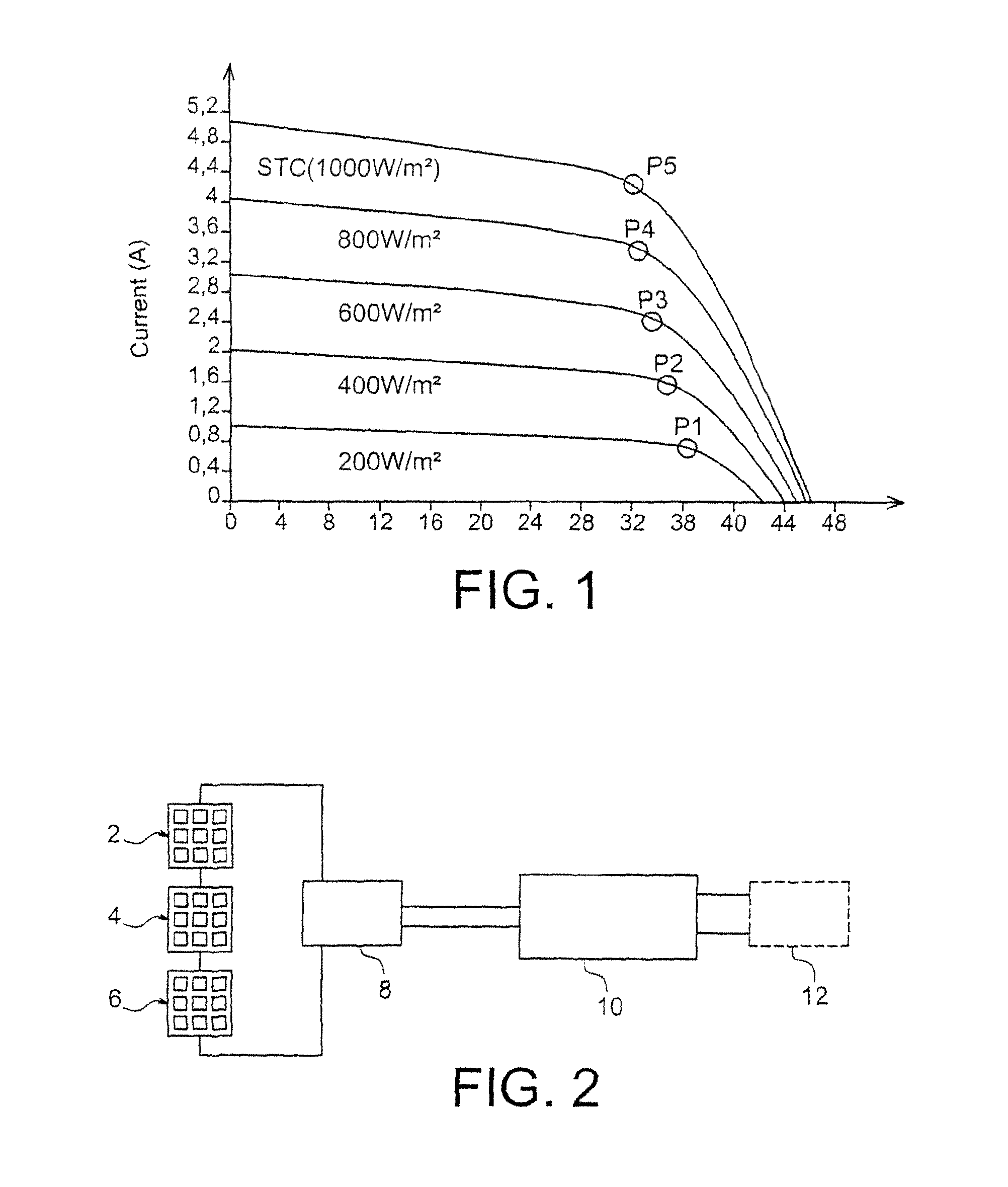
[0055]FIG. 2 illustrates the invention: an electronic limiter is inserted into the electric circuit between a photovoltaic field and a converter.

[0056]Thus, 3 photovoltaic fields 2, 4, 6, a voltage limiter 8 according to the invention, and a converter 10, connected to the electric network 12 are illustrated in this figure. The invention is not limited to three photovoltaic fields, but applies to any number of these fields. Subsequently, in the text, the whole of the voltaic fields will be designated by the single numerical reference 2.

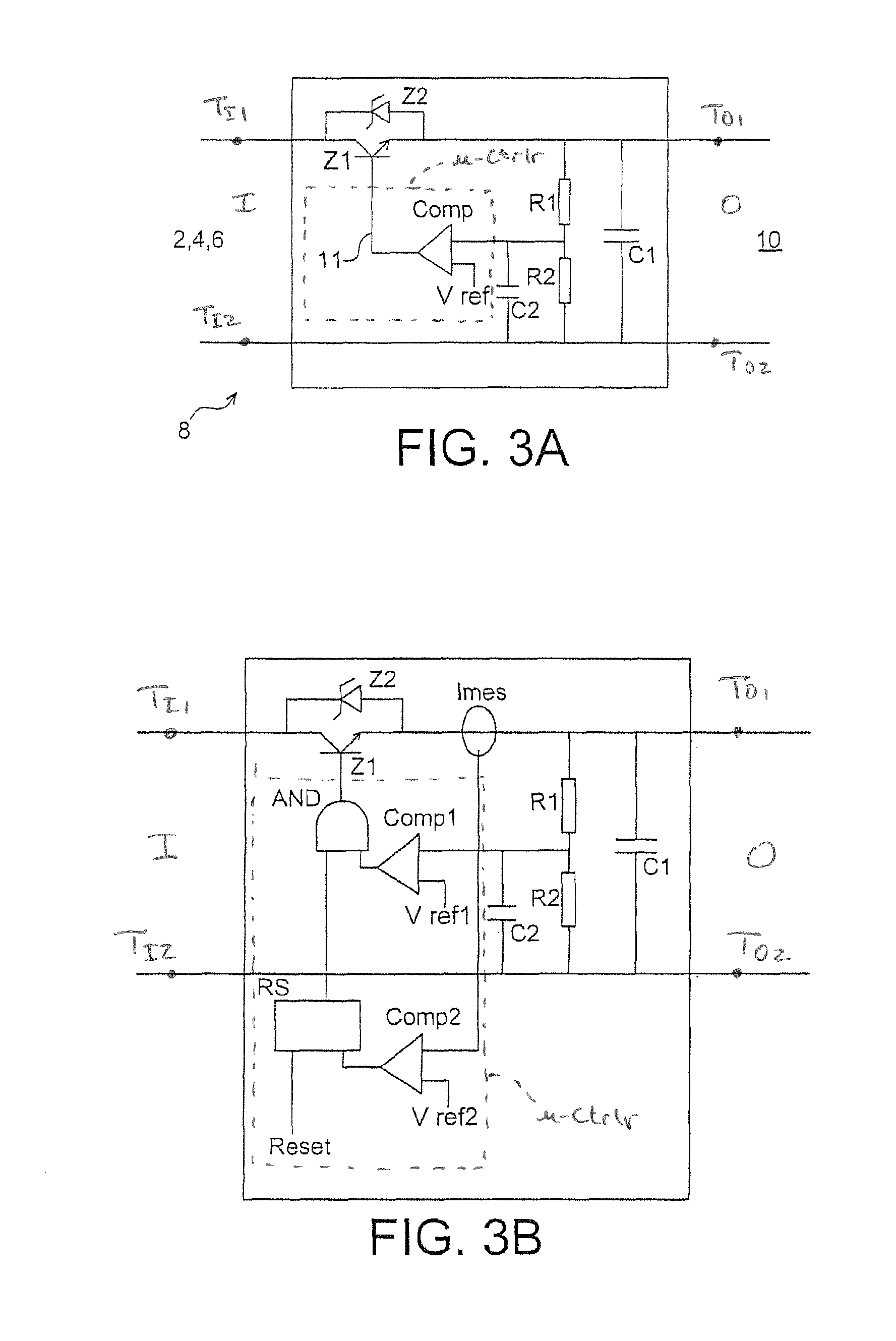
[0057]The voltage limiter device 8 according to the invention is placed between the photovoltaic modules 2 and the power converter 10; it is preferably placed as close as possible to the photovoltaic modules, in order to provide the most effective protection against electric arcs and short circuits.

[0058]The ideal place is an installation directly at the output of the photovoltaic module.

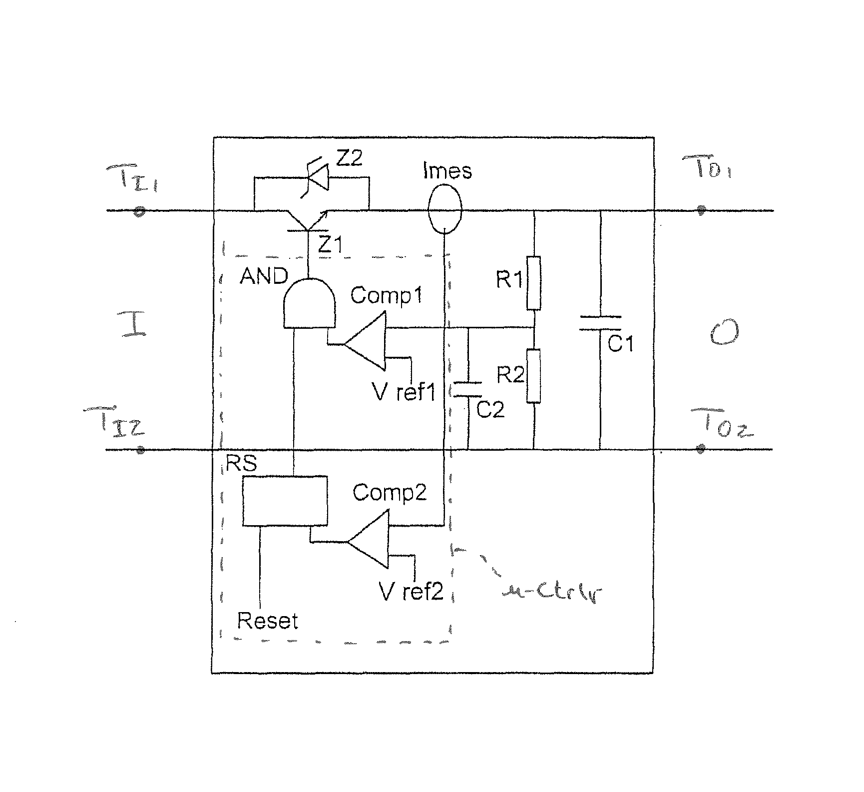
[0059]The limiter device 8 ensures a limitation of the no-load vo...

second embodiment

[0075] the converter 10 is in operation, as well as the photovoltaic field 2, 4, 6.

[0076]When the converter is activated, it consumes a substantial current. The voltage at the terminals of C1 decreases very rapidly and passes under the threshold of the reference of the comparator Comp1, and the latter closes the switch Z1. The converter 10 imposes a voltage corresponding to the maximum power being provided by the photovoltaic field. The voltage measured by R1 / R2 therefore does not pass again above the reference value Vref1 since the latter was adjusted for a voltage at the terminals of C1 slightly above the optimum power voltage of the field. The switch Z1 therefore remains permanently closed, thereby powering the converter 10.

[0077]In a third operating mode, there is an opening of the circuit between the limiter device 8 and the converter 10.

[0078]This opening may result from the opening, either accidental or not, of a connector or of an electric connection between the means 8 and ...


PUM


Abstract

A voltage limiter device of an assembly of photovoltaic modules, including: (a) means (Z1) forming an electronic switch for a current of said assembly; (b) comparison means (Comp, R1, R2, C2) for comparing a voltage at the output of the limiter with a reference voltage value (Vref); and (c) means for controlling the means forming an electronic switch, depending on the result of the comparison carried out by the comparison means.

Description

CROSS REFERENCE TO RELATED APPLICATIONS or PRIORITY CLAIM[0001]This application is a national phase of International Application No. PCT / EP2008 / 051947, entitled “VOLTAGE LIMITER AND PROTECTION FOR A PHOTOVOLTAIC MODULE”, which was filed on Feb. 18, 2008, and which claims priority of French Patent Application No. 07 53383, filed Feb. 20, 2007.TECHNICAL FIELD AND PRIOR ART[0002]The invention relates to an electronic device of the voltage limiter type. It advantageously applies to one or more photovoltaic modules, to which it provides protection.[0003]Presently, 3 types of photovoltaic modules are mainly known: monocrystalline, polycrystalline and amorphous types. The amorphous technology has certain advantages, notably in terms of flexibility and of the small amount of materials used.[0004]The voltage and the current produced by photovoltaic modules depend on several parameters (period of sunshine, temperature), and they may vary significantly.[0005]FIG. 1 shows the typical characteri...

Claims


Application Information

Patent Timeline
Patent Type & Authority Patents(United States)
IPC IPC(8): G05F1/571
CPCH02H3/08H01L31/02021H02H7/20Y02E10/50
Inventor PERICHON, PIERRECHATROUX, DANIEL
Owner COMMISSARIAT A LENERGIE ATOMIQUE ET AUX ENERGIES ALTERNATIVES
Why Eureka
Try Eureka