Patient interface systems

a patient interface and system technology, applied in the field of patient interface systems, can solve problems such as health risks, lack of stability, and improvement or decrease of comfort or effectiveness, and achieve the effect of convenient use of headgear assemblies and comfor

Active Publication Date: 2013-11-05
RESMED LTD
View PDF93 Cites 76 Cited by
  • Summary
  • Abstract
  • Description
  • Claims
  • Application Information

AI Technical Summary

Benefits of technology

[0029]One aspect of the present technology is a quiet comfortable patient interface for treatment of respiratory disorders. Another aspect of the present technology is a comfortable and easier to use headgear assembly. Another aspect of the present technology is a system of indicating headgear positioning. Another aspect of the present technology is a quiet vent for a respiratory mask.
[0030]A headgear assembly in accordance with the present technology may be moulded from an elastomer such as liquid silicone rubber. Moulded headgear comfort may be improved by increasing the surface roughness of surfaces in contact with the skin, such as the face. Moulded headgear comfort may also be improved by increasing the radius of edges of moulded strap. Moulded headgear comfort may also be improved by locating parting lines further away from patient skin contacting portions. Moulded headgear comfort may also be improved by the addition of textiles, for example, by wrapping textiles around a moulded strap. Moulded headgear ease of use may be improved by increasing surface roughness in certain regions, for example those surfaces which may contact bedding. In other regions, for example, where a portion of headgear strap may be required to lock with another, an increased stickiness may be advantageous. Ease of use of headgear straps may be improved by including visual or tactile features on a strap to indicate position in a locking arrangement. For example, a tactile feature may be moulded into a strap end which facilitates patient appreciation of the adjustment position of the strap.
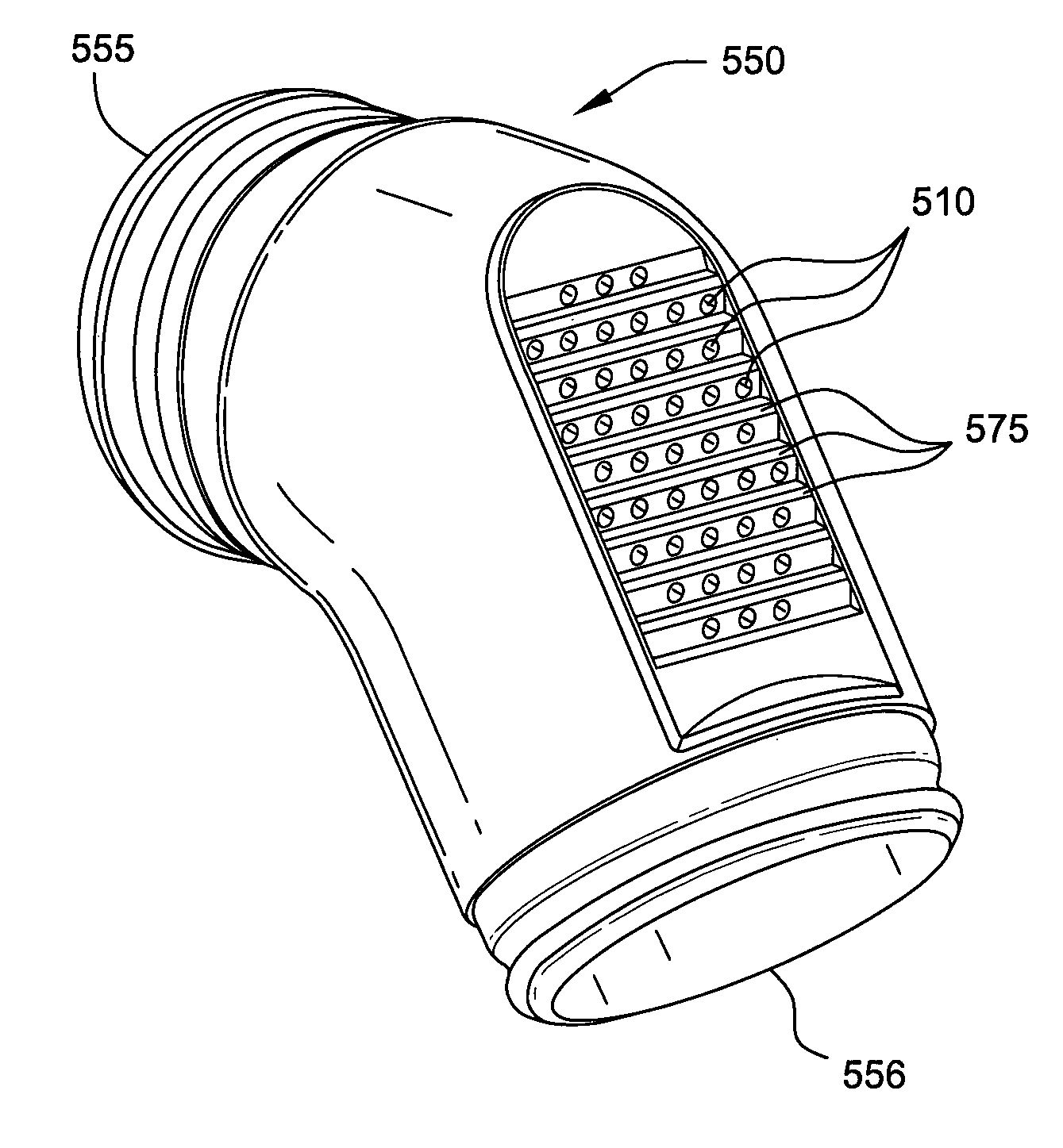
[0031]In some mask systems, it may be desirable to have a vent made from an array of small holes and to have the air vent in a direction that is not orthogonal to the surface in which the vent is located. In accordance with the present technology, a vent is provided where adjacent rows of holes are arranged in a progressively displaced configuration. Another aspect of the present technology is to have a vent hole having at least a portion of an inlet and or outlet cross-section having a rounded edge. Another aspect of the present technology relates to an air directing structure in an elbow that may direct incoming air away from an inner wall where for example may be positioned vent holes and may also increase the length of the vent holes by thickening the wall section of the part where the vent holes are positioned, while maintaining a thinner wall section of the part where it needs to flex into engagement with an air delivery tube.

Problems solved by technology

Apparently subtle changes may improve or decrease comfort or effectiveness.
While millions of people suffer from the condition of sleep disordered breathing, many fail to comply with therapy because of problems with comfort, ease of use, stability, leak, and obtrusiveness, and thus expose themselves to health risks.
Whilst some smaller patient interfaces (such as some nasal puffs, and some nasal prongs) may be less obtrusive than larger masks (such as a full-face mask) they can suffer from a lack of stability.
This can lead to excessive forces on sensitive regions of the face, resulting in discomfort to the patient.

Method used


Image

  • Patient interface systems
  • Patient interface systems
  • Patient interface systems

Examples


sixth embodiment

[0251]Referring to FIGS. 14a and 14b, according to another sample embodiment, the seal positioning and stabilizing structure 36 may be formed of a single piece, including the top strap 40, the rear strap 42, the side strap 38 and the lateral side arms 68. A buckle 71 may be provided on the top strap 40 to adjust the fit of the seal positioning and stabilizing structure 36 to the patient. It should be appreciated that the buckle may be provided additionally or alternatively to the rear strap 42. The single piece seal positioning and stabilizing structure 36 may be connected to the patient interface structure 32 by connectors such as hook and loop fasteners. Alternatively, the single piece seal positioning and stabilizing structure 36 may be a complete circular component that can wrap around the patient interface structure 32 at, for example, the base of the patient interface structure 32 between the patient interface structure 32 and the elbow 17, or at the top of the patient interfa...

seventh embodiment

[0253]Referring to FIGS. 15a and 15b, according to another sample embodiment, the side strap 38, the top strap 40, and the rear strap 42 of the seal positioning and stabilizing structure 36 are connected by a connector 72. The side strap 38 may be connected to the patient interface structure 32 by a seal positioning and stabilizing structure connector 12 which is provided on the patient interface structure 32. The patient interface structure 32 may be connected directly to an air delivery tube 16 by a swivel elbow 17. The connector 72 allows the position of each of the straps 38, 40, 42 to be adjusted to allow the patient to affect a seal between the patient interface structure 32 and the airways of the patient and allows the seal positioning and stabilizing structure 36 to be sized and fitted to a variety of patients.

3.3.8 Seal Positioning and Stabilizing Structure

eighth embodiment

[0254]FIGS. 24m-24q show a patient interface assembly including an eighth embodiment of a seal positioning and stabilizing structure. The seal positioning and stabilizing structure includes a main strap loop 74, and rear strap 85. With reference to FIG. 24q main strap loop 74 includes a strap connector 82 arranged to connect rear strap 85 at an angle A with respect to the crown engaging top portion main loop 74 of about 90° to about 140°, preferably about 95° to about 110°, most preferably about 100°. The closer the angle A is to the preferred values there is a progressive improvement in the fit range of the headgear, allowing the patient interface to comfortably fit a range from smaller to larger heads.

[0255]With further reference to FIGS. 24q, 16a and 16d, the main strap loop 74 has a curved middle portion in between two generally straight portions. The first straight portion lies over the crown of the patient's head in use. The second straight portion has one end connected with a...


PUM


Abstract

A headgear for use with a patient interface for delivering a flow of breathable gas to a patient includes at least a strap (741) adapted to position the patient interface in sealing engagement with the patient's airways. The strap is constructed from an elastomer and a first side of the strap includes a first region (215) on a portion of its surface that is textured to reduce friction with objects contacting the strap. A textured surface coating for a portion of an elastomer strap included in a headgear system is adapted to contact the skin of a patient, when in use, and the coating has a Ra value greater than zero. A vent (500) for use with a patient interface for delivering a flow of breathable gas to a patient includes a plurality of rises (580) and runs (570) in a stepped arrangement; and a plurality of holes (510) in the stepped arrangement for the venting of gas.

Description

CLAIM FOR PRIORITY[0001]This application is the U.S. national phase of International Application No. PCT / AU2010 / 001004, filed Aug. 6, 2010, which designated the U.S. and claims priority to Australian Applications 2009903686 and 2009904389, filed Aug. 7, 2009 and Sep. 9, 2009, respectively, and is a continuation-in-part of U.S. application Ser. No. 12 / 763,467, filed Apr. 20, 2010, the entire contents of each being incorporated herein by reference.CROSS REFERENCE TO RELATED APPLICATIONS[0002]U.S. application Ser. No. 12 / 763,467 is a continuation-in-part of International Application PCT / AU2008 / 001557, filed Oct. 22, 2008, which claims priority to Australian Applications 2007905737 and 2007906276, filed Oct. 22, 2007 and Nov. 16, 2007, respectively, and U.S. Applications 61 / 031,173 and 61 / 129,982, filed Feb. 25, 2008 and Aug. 4, 2008, respectively, the entire contents of each being incorporated herein by reference. U.S. application Ser. No. 12 / 763,467 is also a continuation-in-part of U...

Claims


Application Information

Patent Timeline
Patent Type & Authority Patents(United States)
IPC IPC(8): A62B9/04A61M16/00A62B18/08
CPCA61M16/06A61M16/0666A61M16/0683A62B9/04A61M16/0611A61M16/0816A61M2205/42A61M2210/0618A61M16/0825A61M16/0622
Inventor RUMMERY, GERARD MICHAELHENRY, ROBERT EDWARDHILL, PHOEBE KATHERINEHURST, ANDREWNURSE, PHILIP MICHAEL
Owner RESMED LTD
Why Eureka
Try Eureka