Lifting system and method for lifting bulk sized, high weight objects

a technology which is applied in the field of lifting system and lifting method, or elevating, bulk-sized, heavy-weight objects, can solve the problems of time-consuming, slow, cumbersome technique, etc., and may require considerable manpower in placing and operating the piston jack

Active Publication Date: 2013-11-05
RASHALL RICHARD J
View PDF7 Cites 4 Cited by
  • Summary
  • Abstract
  • Description
  • Claims
  • Application Information

AI Technical Summary

Benefits of technology

[0012]In operation, the system is positioned with each piston assembly placed such the lifting plate is under the lifting point(s) of the object to be raised. Hydraulic conduit lines are sealingly connected to the piston assembly at one end and to a control panel having a source of hydraulic fluid in communication therewith. Thereafter, pressure is increased in the hydraulic conduit lines by signal from the hydraulic control panel and the piston assembly is telescopically expanded and the object lifted a comparative distance to the required height to enable the transport mechanism or trailer to be moved under the object. A signal from the control panel is then initiated and the hydraulic fluid pressure reduced to enable the hydraulic fluid flow to be reversed from the piston assembly to a source or body of control fluid such that the piston is enabled to telescopically contract relative to the respective cylindrical housing a short distance. The object now is safely and completely resting on the transport mechanism or vehicle and may be moved from the initial location to another location.

Problems solved by technology

As will be appreciated, this technique is not only cumbersome, but is time consuming, and slow.
This technique also may require considerable man power in placing and operating the piston jacks, as well as the placement and removal of the stacks of cylinder or cement or wood blocks.

Method used


Image

  • Lifting system and method for lifting bulk sized, high weight objects
  • Lifting system and method for lifting bulk sized, high weight objects
  • Lifting system and method for lifting bulk sized, high weight objects

Examples


Embodiment Construction

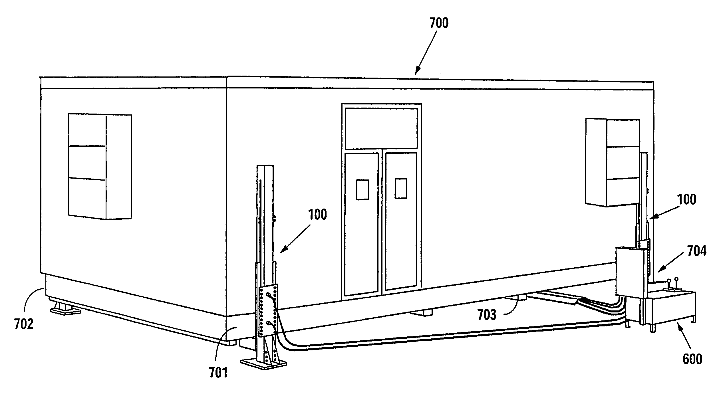
[0030]Now with first reference to FIGS. 9, 10 and 11, the system 100 of the present invention comprises a carriage assembly 500, a housing 200, a piston assembly 400, and a base 300. A control panel 600 (FIG. 11) includes hydraulic controls 601 and 602 for control of pressure in hydraulic lines or conduits 604, 608 (FIG. 15) having respective threaded and sealing ends 607 for connection to receiving ports or connectors on a control box 603 (FIG. 11). The hydraulic conduits 604, 608, are of known construction and commercially available from a number of sources. Likewise, the control panel 600 is of general and known construction and is also commercially available from a number of sources. For example, such components are readily available from ENERPAC, Inc. (web site: www.enerpac.com), as the “SLS-Series, Synchronous Lift” System. This hydraulic system can provide and accommodate from 1 ton to 100 tons of lift force per lifting point.

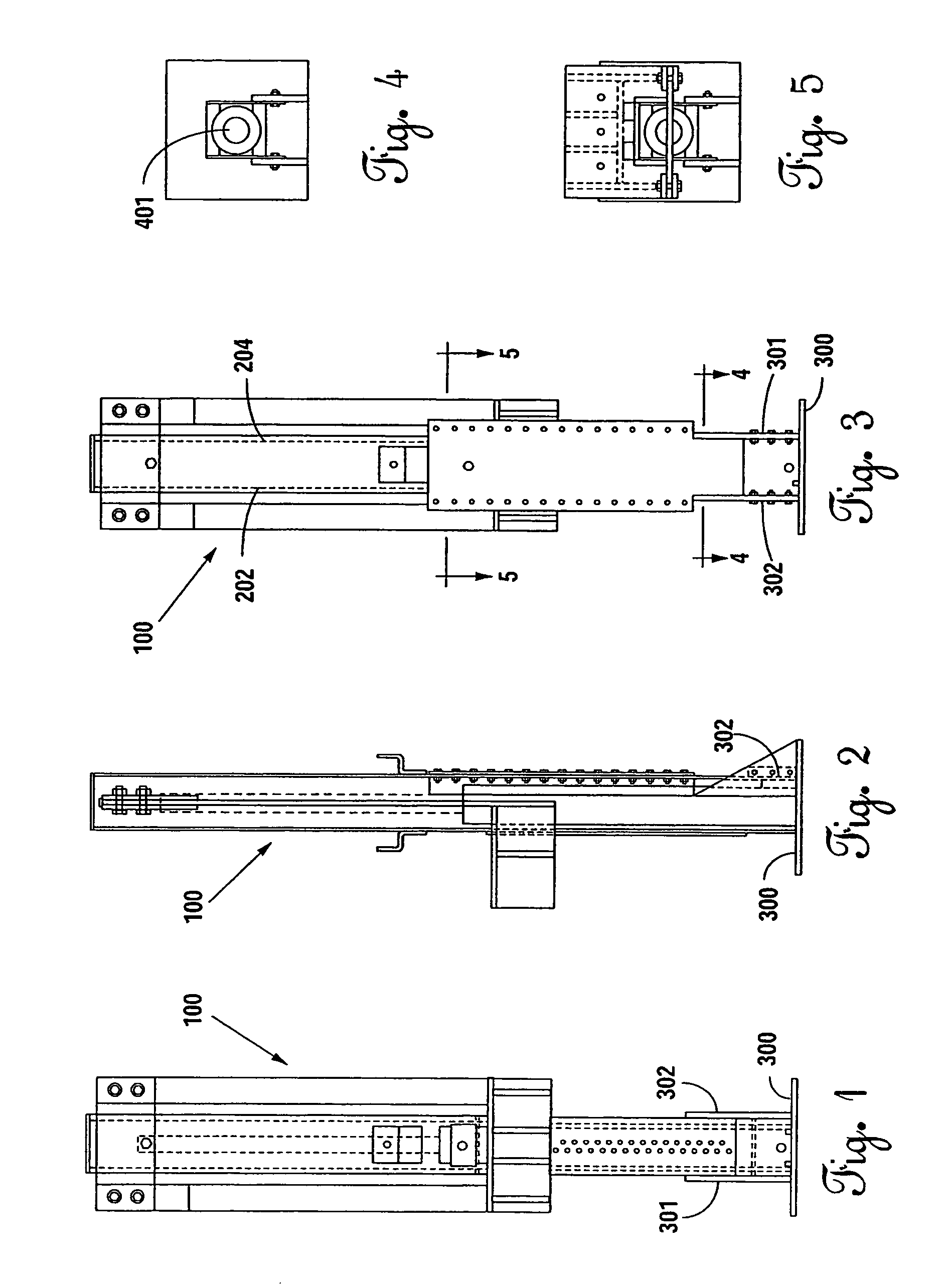
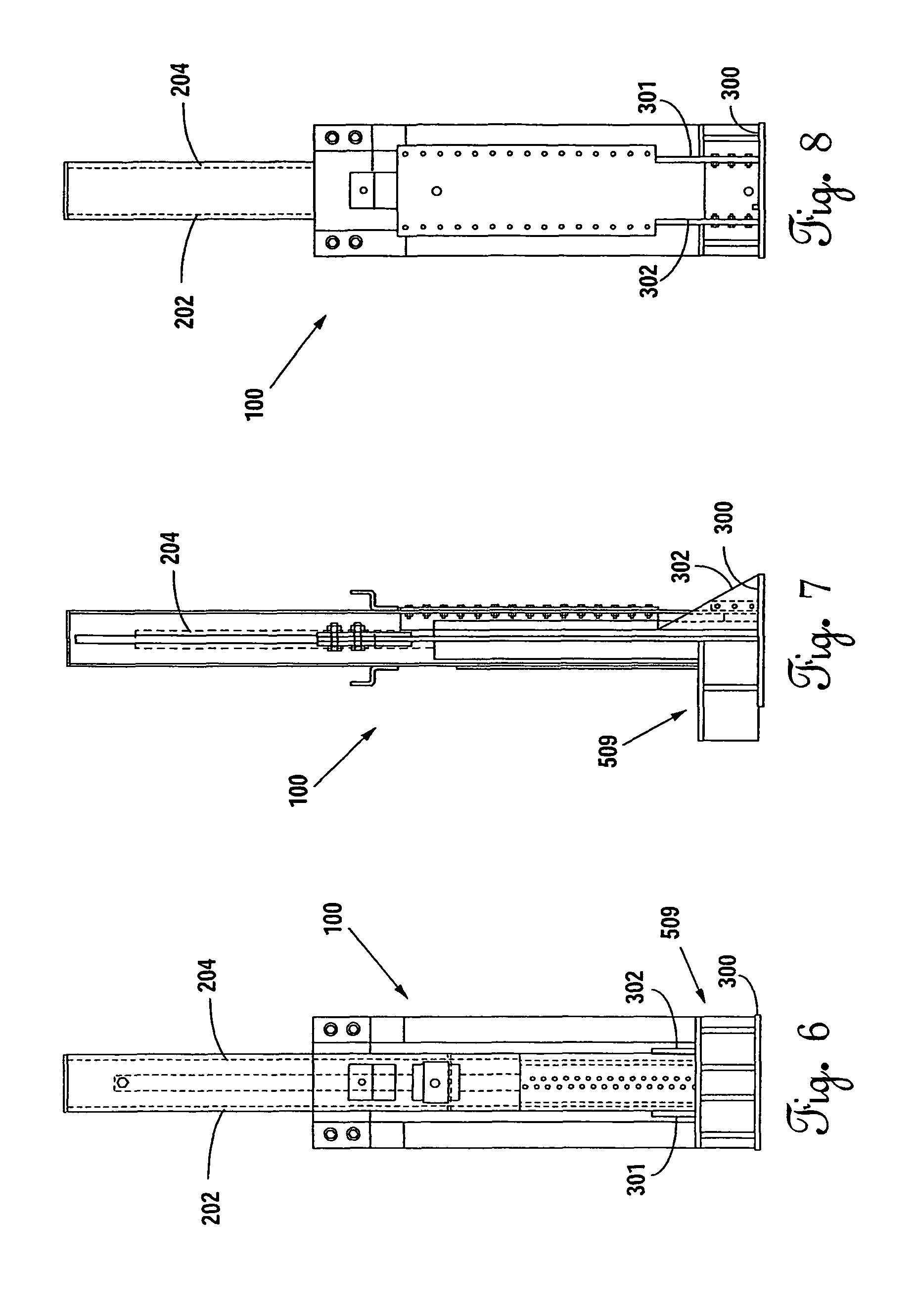
[0031]Now referring to FIGS. 1 through 9, and, par...


PUM


Abstract

A lifting system and method are disclosed for lifting bulk sized, extremely high weight objects, such as a house, other buildings, skids, chemical plant modules, refinery modules or storage facility, or the like, from one position to another position. The system includes at least one cylinder housing a respective hydraulically actuated, telescoping piston. A lifting plate having an upper face is in operable communication with the piston and is further horizontally offset from the respective piston whereby, when the lifting system is positioned for lifting the high weight object, each of the upper faces may be positioned in close proximity to the ground and under the high weight object at the lifting points, without positioning any of the pistons under the high weight object. A method of operation is also disclosed.

Description

CROSS REFERENCE TO RELATED APPLICATION[0001]This application is a utility application and claims priority to provisional patent application No. 61 / 335,375 filed on Jan. 6, 2010.BACKGROUND OF THE INVENTION[0002](1) Field of the Invention[0003]The invention is directed to a system and method for lifting, or elevating, bulk-sized, heavy weight objects, such as buildings, skids, chemical plant modules, refinery modules, storage facilities, and the like.[0004](2) Brief Description of the Prior Art[0005]Bulk sized, or extremely high weight objects include power generator stations, pre-fabricated and other buildings, water and sewage treatment facilities, chemical plant modules, refinery modules, and the like. These objects may be several stories high and / or weigh tens, or even hundreds of tons. Most, but not all, of these facilities are built to be used at one location for a specified amount of time, and then transported, either by barge, ship, truck, rail to another, often remote, locati...

Claims


Application Information

Patent Timeline
Patent Type & Authority Patents(United States)
IPC IPC(8): B60S9/02
CPCB66F3/24B66F3/46
Inventor RASHALL, RICHARD J.
Owner RASHALL RICHARD J
Why Eureka
Try Eureka