
Offset compensation apparatus for magnetic detection circuit and method thereof

a compensation apparatus and magnetic detection technology, applied in the direction of galvano-magnetic amplifiers, instruments, magnetic measurements, etc., can solve the problems of distorted operating points in a region beyond (or outside) the range, and the detection of erroneous magnetic signals

Inactive Publication Date: 2013-11-05
SAMSUNG ELECTRO MECHANICS CO LTD
View PDF5 Cites 2 Cited by
  • Summary
  • Abstract
  • Description
  • Claims
  • Application Information

AI Technical Summary

Benefits of technology

Enables real-time detection and compensation of offsets, preventing distortion in output voltage and allowing for effective cancellation of large offsets during magnetism detection, applicable to both linear and switch Hall IC structures without the need for an auto-zero scheme.

Problems solved by technology

However, the majority of Hall elements are fabricated to be non-uniform, so, although a magnet is not let to approach, a potential difference is made between the other remaining counter electrodes to which a current is not applied, resulting in that magnetism is erroneously detected as if there was a magnet nearby.
However, in the prior art, since the magnetic offset is amplified through the amplifying unit, the offset can be canceled only within a range in which the offset is not saturated through a gain of the amplifying unit, causing a problem in which an operating point is distorted at a region beyond (or outside) the range.

Method used


Image

  • Offset compensation apparatus for magnetic detection circuit and method thereof
  • Offset compensation apparatus for magnetic detection circuit and method thereof
  • Offset compensation apparatus for magnetic detection circuit and method thereof

Examples


Embodiment Construction

[0027]Various features and advantages of the present invention will be more obvious from the following description with reference to the accompanying drawings.

[0028]The terms and words used in the present specification and claims should not be interpreted as being limited to typical meanings or dictionary definitions, but should be interpreted as having meanings and concepts relevant to the technical scope of the present invention based on the rule according to which an inventor can appropriately define the concept of the term to describe most appropriately the best method he or she knows for carrying out the invention.

[0029]The above and other objects, features and advantages of the present invention will be more clearly understood from the following detailed description taken in conjunction with the accompanying drawings. In the specification, in adding reference numerals to components throughout the drawings, it is to be noted that like reference numerals designate like component...


PUM


Abstract

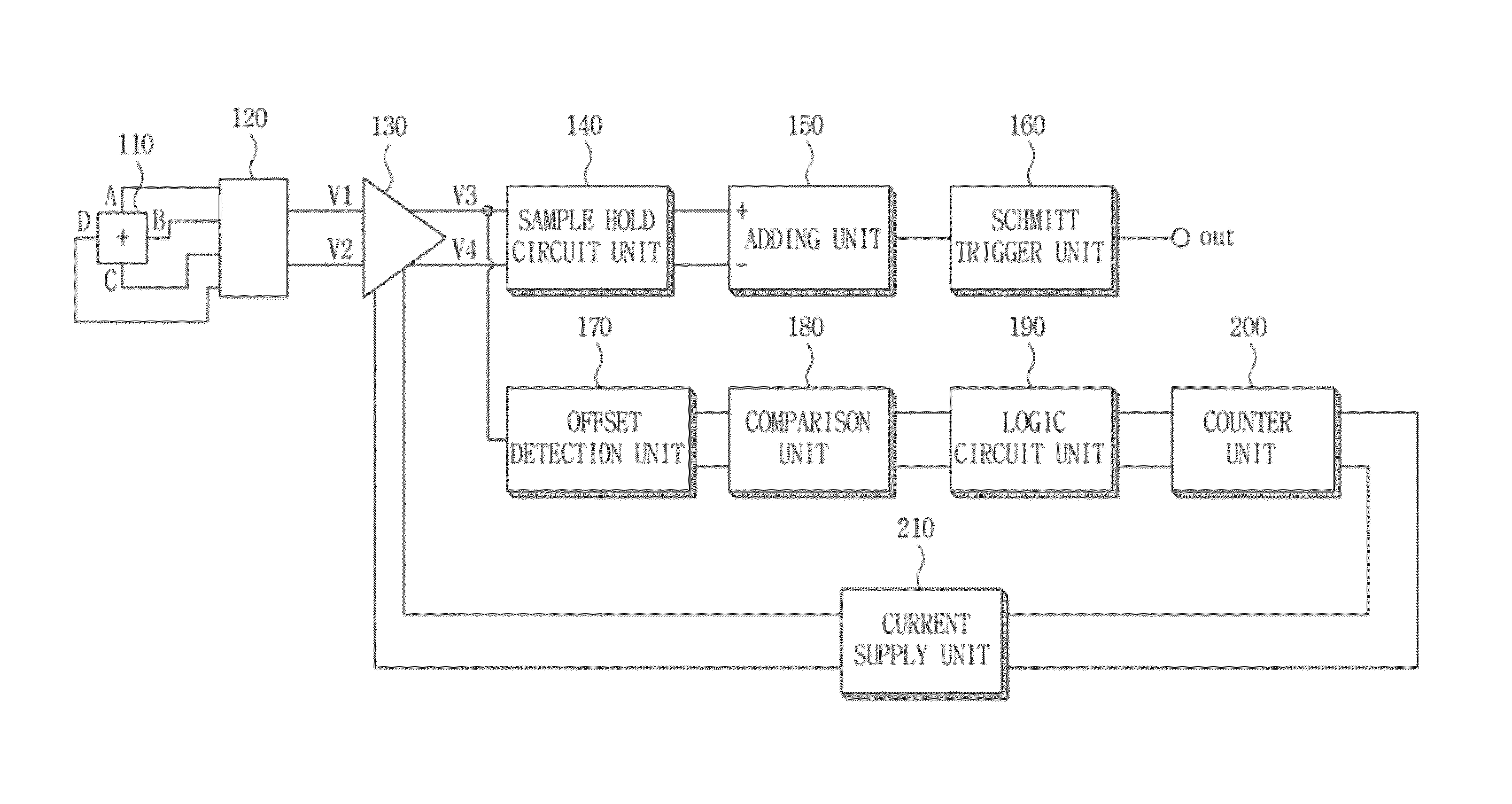
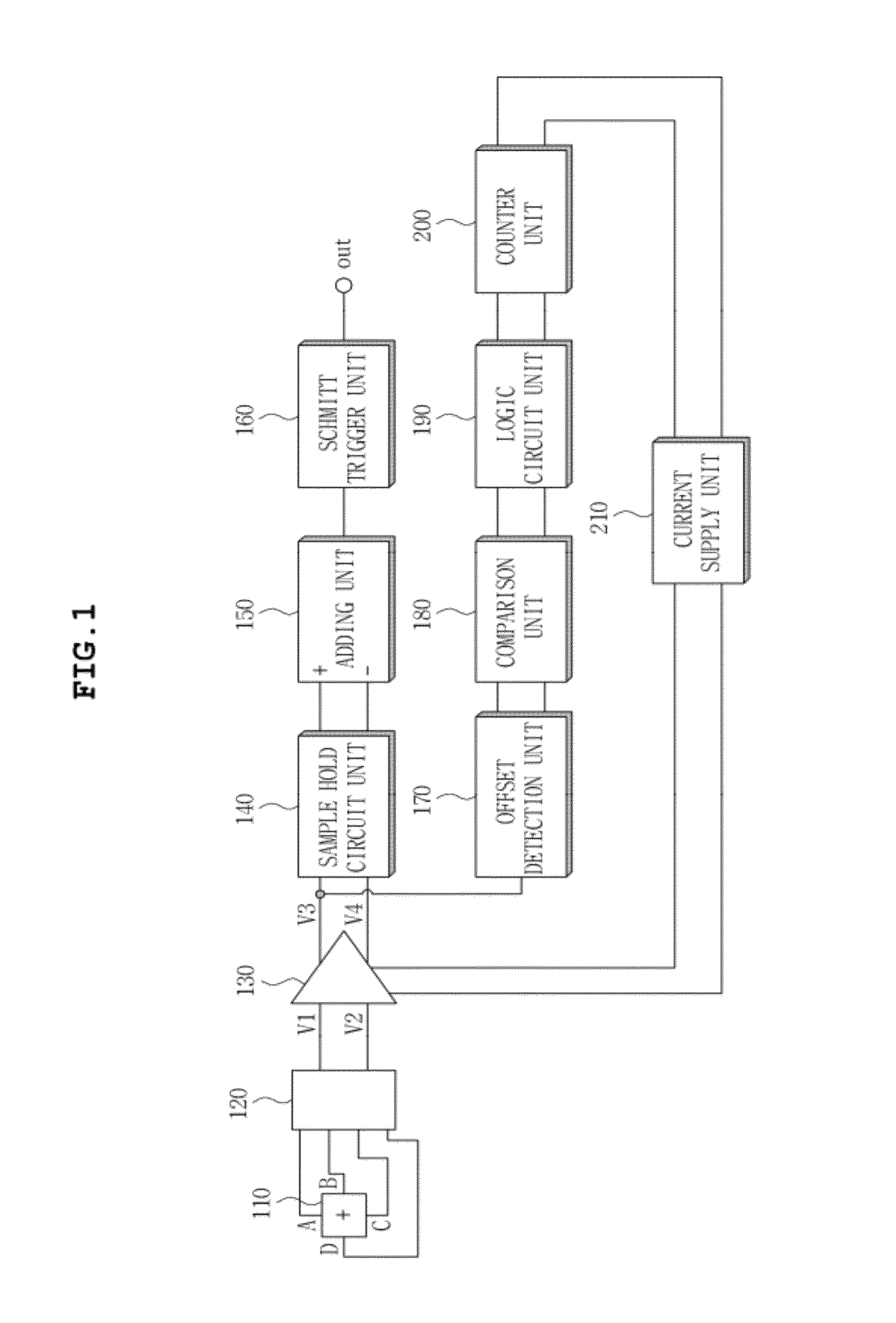
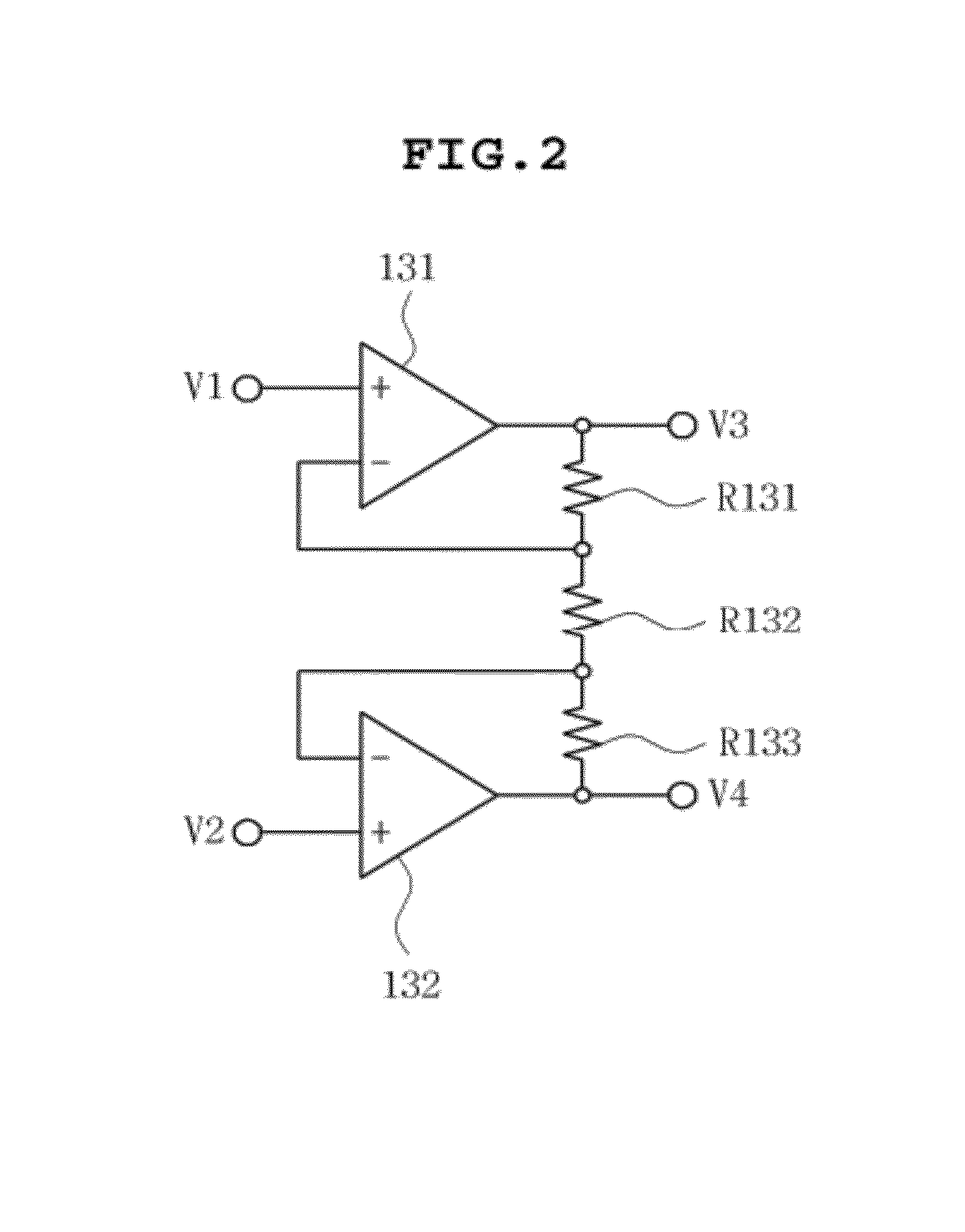
Disclosed herein are an offset compensation apparatus for a magnetic detection circuit, and a method thereof. The offset compensation apparatus includes: an amplifying unit amplifying an output voltage, and outputting the amplified voltages; an offset detection unit detecting an offset; a comparison unit determining whether or not the offset output from the offset detection unit is greater than a pre-set positive reference value or smaller than a pre-set negative reference value; a counter unit; and a current supply.

Description

CROSS REFERENCE TO RELATED APPLICATION[0001]This application claims the benefit of Korean Patent Application No. 10-2011-0039778, filed on Apr. 27, 2011, entitled “Offset Compensation Apparatus for The Magnetic Detection Circuit and Method Thereof”, which is hereby incorporated by reference in its entirety into this application.BACKGROUND OF THE INVENTION[0002]1. Technical Field[0003]The present invention relates to an offset compensation apparatus for a magnetic detection circuit and a method thereof.[0004]2. Description of the Related Art[0005]In a magnetic detection circuit using a Hall element, when a current is applied between any pair of counter electrodes among electrodes formed at four corners of the Hall element and a magnet is let to approach, a potential difference is made between the other remaining counter electrodes to which a current is not applied, thereby detecting magnetism.[0006]However, the majority of Hall elements are fabricated to be non-uniform, so, although ...

Claims


Application Information

Patent Timeline
Patent Type & Authority Patents(United States)
IPC IPC(8): H03F15/00
CPCG01R33/0029G01R15/20G01R33/07
Inventor PYO, SEUNG CHULKIM, KYUNG UK
Owner SAMSUNG ELECTRO MECHANICS CO LTD
Learn More