Display panel

a technology of floating electrodes and display panels, applied in non-linear optics, instruments, optics, etc., can solve the problem that the liquid crystal molecules near the upper substrate may not be completely twisted in the conventional fes lcd panel, and achieve the effect of increasing the capacitance coupling

Active Publication Date: 2013-11-05
AU OPTRONICS CORP
View PDF4 Cites 0 Cited by
  • Summary
  • Abstract
  • Description
  • Claims
  • Application Information

AI Technical Summary

Benefits of technology

[0007]The invention provides a display panel capable of increasing capacitance coupling effect between the floating electrode and the pixel electrode in a FES LCD panel.
[0009]According to the aforementioned, the spacer is disposed between the first plate and the second plate to reduce the distance between the floating electrode and the pixel electrode. As a result, the capacitance coupling effect between the floating electrode and the pixel electrode is increased, the floating electrode can have a sufficient voltage level, and thereby the electric field between the floating electrode and the pixel electrode is strong enough. Therefore, the problem of the liquid crystal molecules near the upper substrate may not be completely twisted in the conventional FES LCD panel can be resolved.

Problems solved by technology

Therefore, the problem of the liquid crystal molecules near the upper substrate may not be completely twisted in the conventional FES LCD panel can be resolved.

Method used


Image

  • Display panel
  • Display panel
  • Display panel

Examples


Embodiment Construction

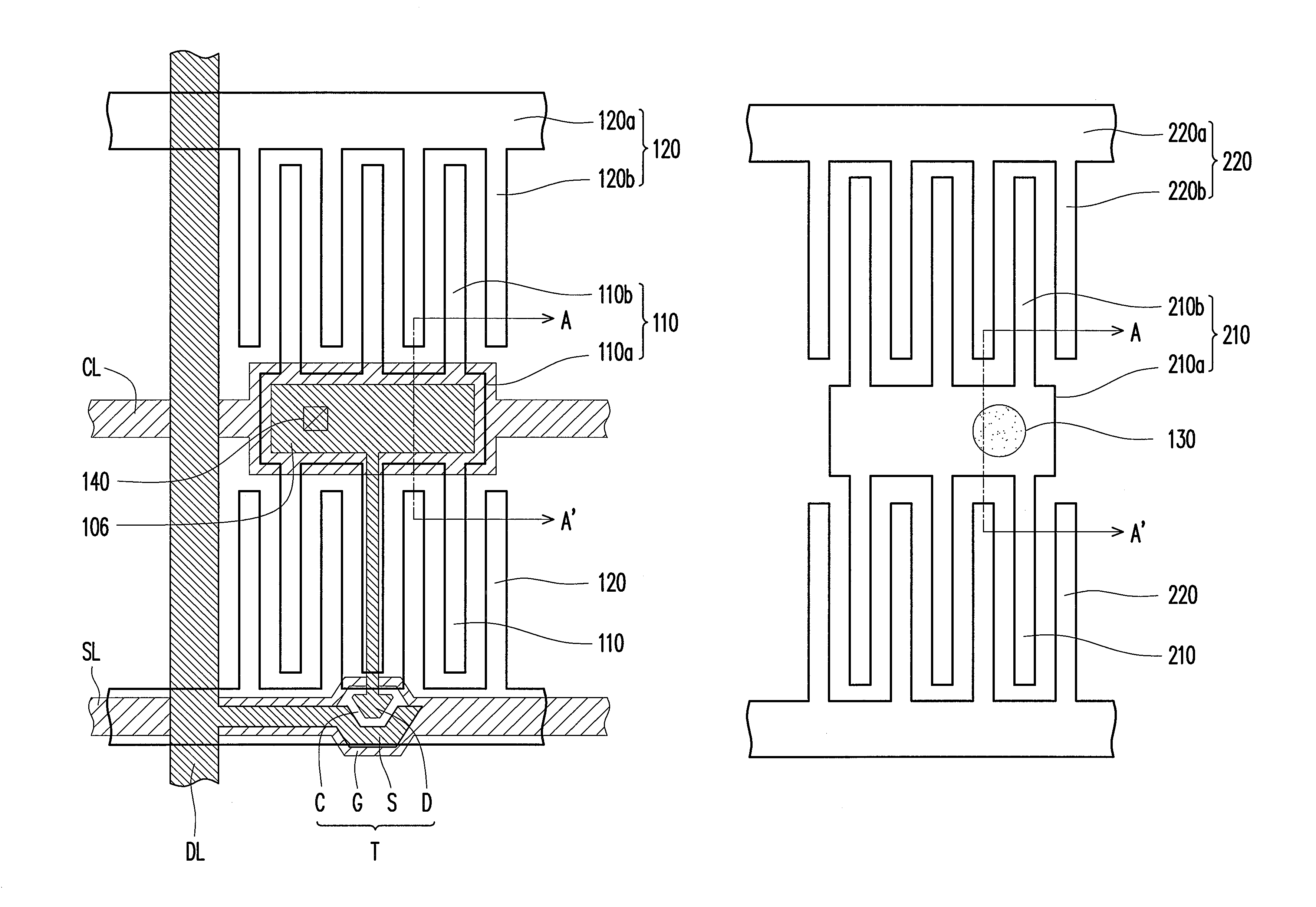
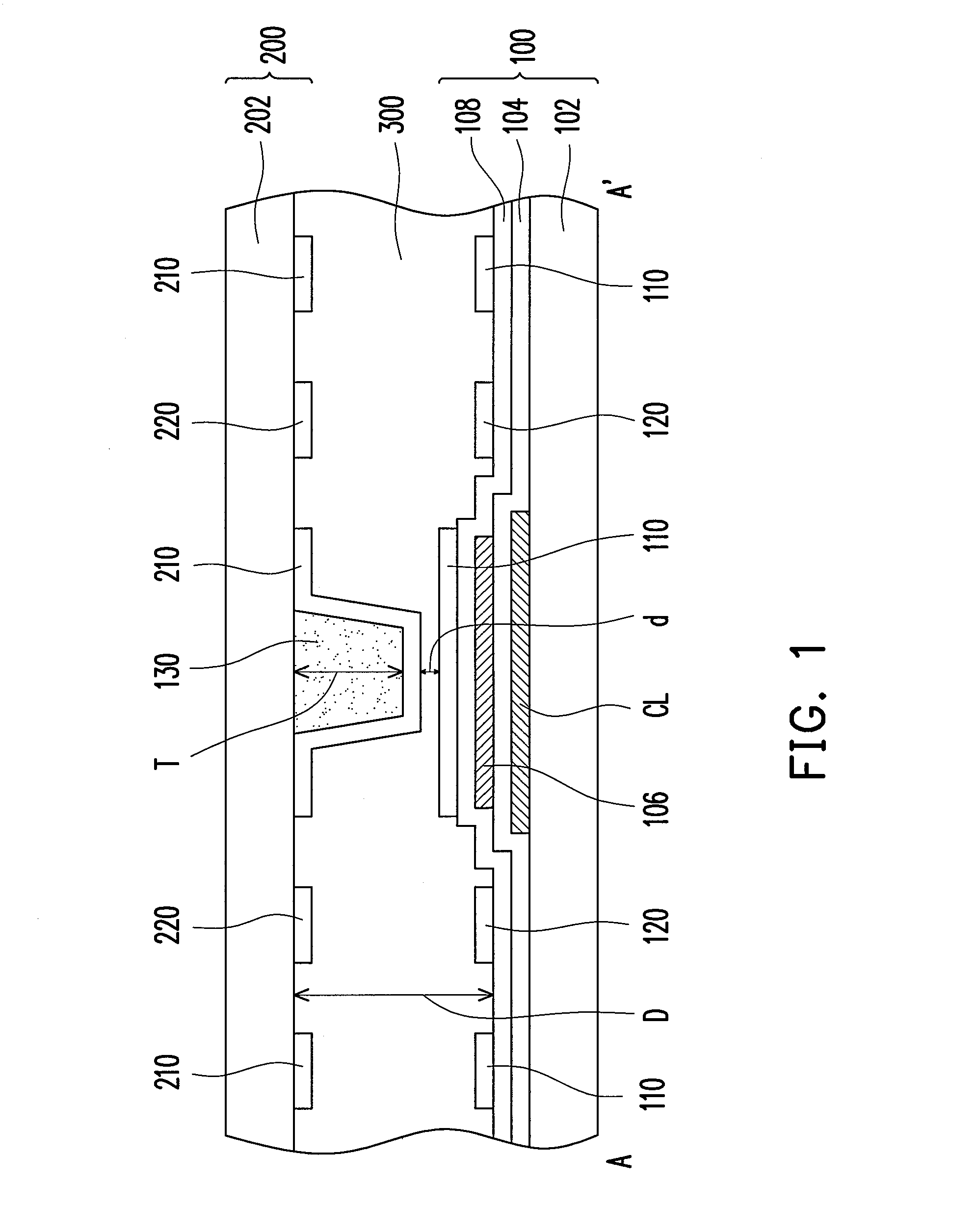
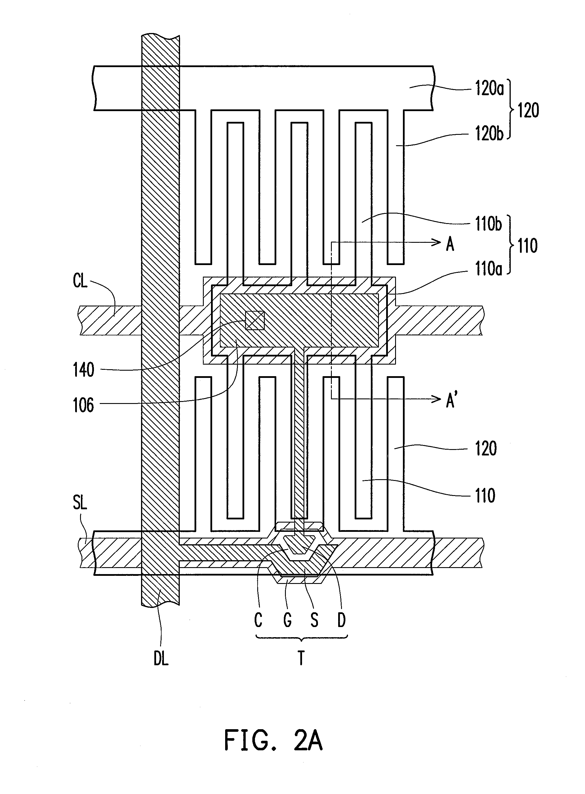
[0017]FIG. 1 is a schematic cross-sectional view of a display panel according to an embodiment of the present invention. FIG. 2A is a top view of the first plate of the display panel in FIG. 1. FIG. 2B is a top view of the second plate of the display panel in FIG. 1. FIG. 1 is a cross-sectional view corresponding to the cross-section line A-A′ in FIG. 2A and FIG. 2B. It is noted that, one pixel structure of the display panel is shown in the drawings for clear illustration. Generally, a display panel is formed by a plurality of pixel structures arranged in an array, and the people skilled in the art can understand the display panel of the present invention according to the description of the specification and the drawings. With reference to FIG. 1, FIG. 2A and FIG. 2B, the display panel of this embodiment includes a first plate 100, a second plate 200, and a spacer 130 and a display medium 300 between the first plate 100 and the second plate 200.

[0018]The first plate 100 comprises a ...


PUM

PropertyMeasurementUnit
thicknessaaaaaaaaaa
insulatingaaaaaaaaaa
common voltageaaaaaaaaaa

Abstract

A display panel including a first plate, a second plate, and a spacer and a display medium between the first plate and the second plate is provided. The first plate has a first substrate, a scan line and a data line on the first substrate, an active device electrically connected to the scan line and the data line, a pixel electrode electrically connected to the active device, and a first common electrode electrically insulated from the pixel electrode and alternatively arranged with the pixel electrode. The second plate has a second substrate, a second common electrode on the second substrate and disposed corresponding to the first common electrode of the first plate, and a floating electrode electrically insulated from the second common electrode and disposed corresponding to the pixel electrode of the first plate.

Description

CROSS-REFERENCE TO RELATED APPLICATION[0001]This application claims the priority benefit of Taiwan application serial no. 99118184, filed on Jun. 4, 2010. The entirety of the above-mentioned patent application is hereby incorporated by reference herein and made a part of this specification.BACKGROUND OF THE INVENTION[0002]1. Field of the Present Invention[0003]The invention relates to a display panel. More particularly, the invention relates to a floating electrode switching (FES) display panel.[0004]2. Description of Related Art[0005]Recently, thin film transistor liquid crystal displays (TFT-LCDs) equipped with superior properties such as high contrast ratio, no gray scale inversion, high luminance, high color saturation, high response speed and wide viewing angle have become mainstream display products in the market. At the current stage, LCD panel technologies that have been developed to satisfy the requirement of a wide viewing angle include: twisted nematic (TN) LCD panels equ...

Claims


Application Information

Patent Timeline
Patent Type & Authority Patents(United States)
IPC IPC(8): G02F1/1333G02F1/1343
CPCG02F1/13394G02F1/134363
Inventor LI, MING-CHUNHUANG, HONG-JILEE, SEOK-LYUL
Owner AU OPTRONICS CORP
Why Eureka
Try Eureka