System and method for determining and controlling focal distance in a vision system camera

a technology of vision system and focal distance, applied in the direction of camera focusing arrangement, printers, instruments, etc., can solve the problems of unreliable technique, liquid lens calibration and focus may lose, time and effort that takes away from runtime operation,

Active Publication Date: 2013-11-05
COGNEX CORP
View PDF10 Cites 107 Cited by
  • Summary
  • Abstract
  • Description
  • Claims
  • Application Information

AI Technical Summary

Benefits of technology

[0009]Illustratively, the calibration target can define alternating transparent and opaque regions and can be illuminated (e.g. backlit by an LED illuminator). This target is illustratively oriented along an acute slant angle with respect to a plane perpendicular to the orthogonal axis so that pattern elements of the target (e.g. parallel lines) are each associated with a predetermined focal distance. For a given focal distance, the sharpness of a plurality of adjacent line pairs is evaluated. The sharpest pair represents the current focal distance. An intervening calibration assembly lens can resolve the light rays from the calibration target before they strike the beam splitter so as to provide the desired range of focal distances at the sensor (e.g. 20 cm-2 m (or infinity)). Illustratively the target can be illuminated by light of a predetermined wavelength (visible or non-visible), and the focus process distinguishes the predetermined wavelength so that calibration can potentially run without interfering with regular runtime imaging of objects.

Problems solved by technology

In addition, the cost of the lens and / or the available space for mounting the vision system can also drive the choice of lens.
However, due to thermal drift and other factors, the liquid lens may lose calibration and focus over time.
However, this requires time and effort that takes away from runtime operation, and can be an unreliable technique (depending in part on the quality of illumination and contrast of the imaged scene).

Method used


Image

  • System and method for determining and controlling focal distance in a vision system camera
  • System and method for determining and controlling focal distance in a vision system camera
  • System and method for determining and controlling focal distance in a vision system camera

Examples


Embodiment Construction

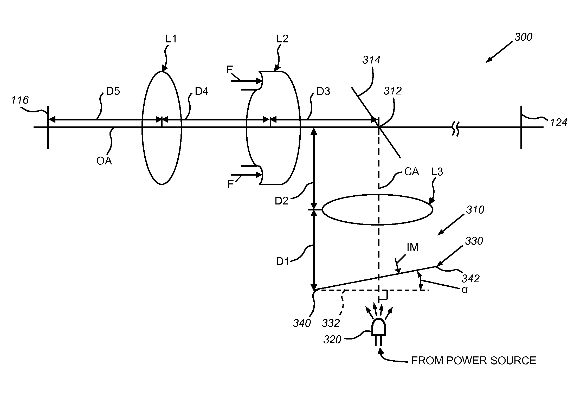
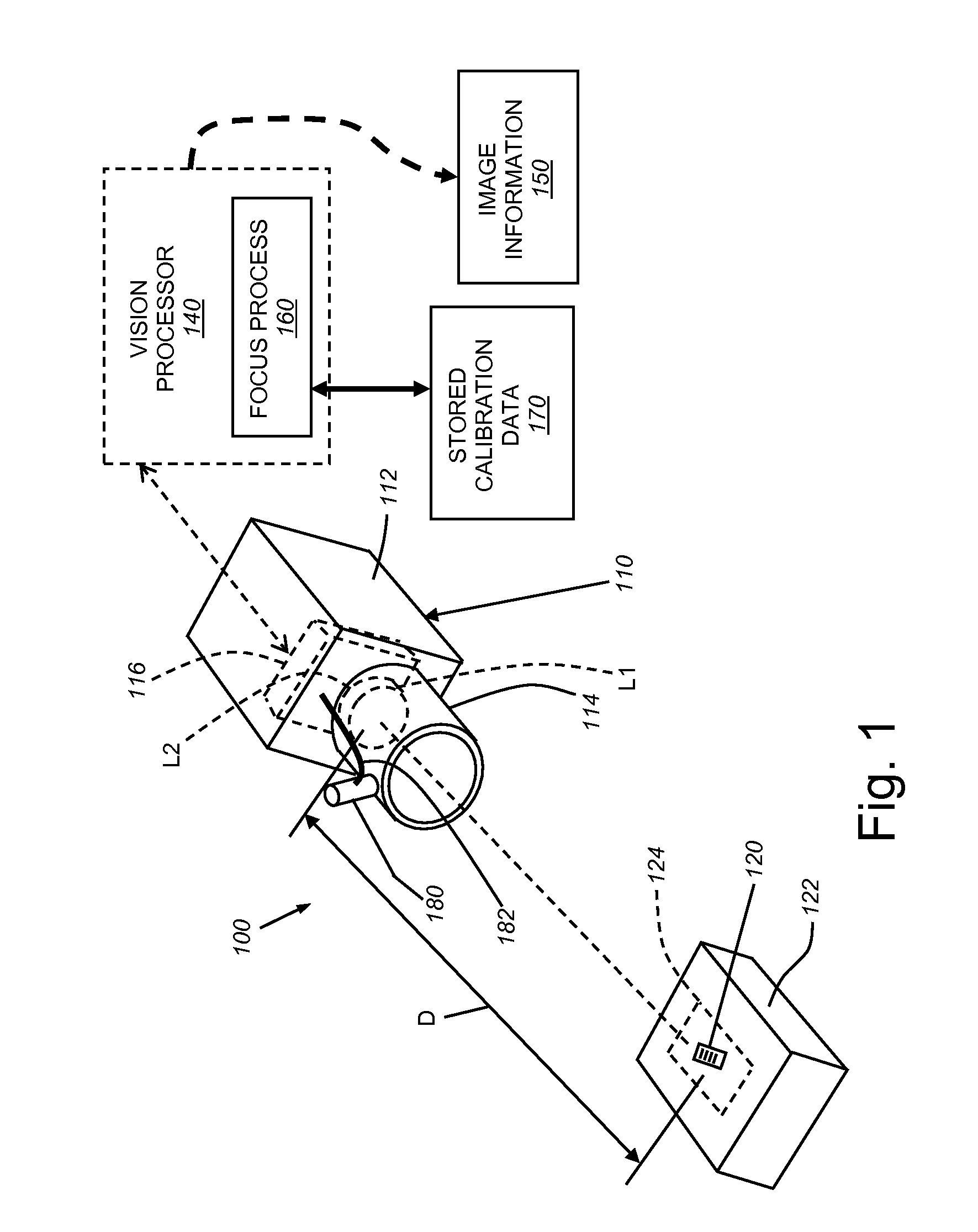
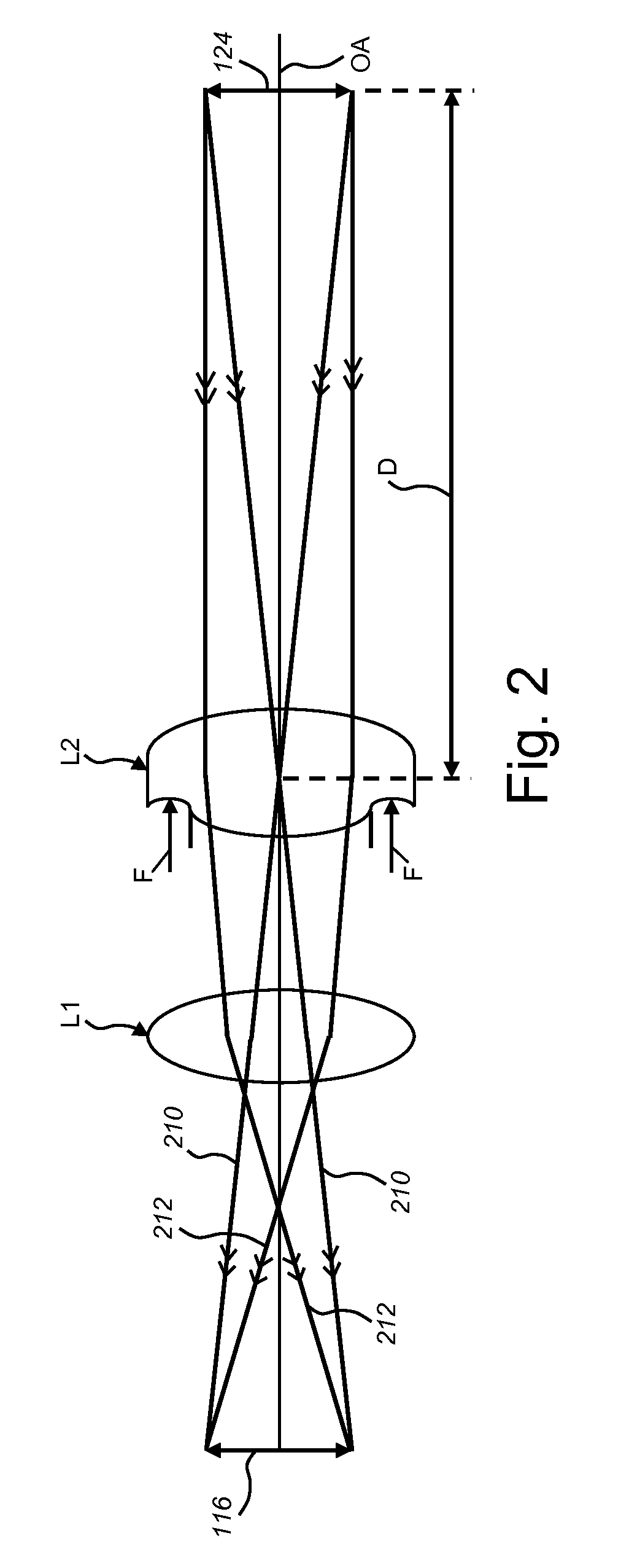
[0022]FIG. 1 shows a vision system arrangement 100 according to an illustrative embodiment. The arrangement 100 includes a vision system, camera 110 having a camera body 112 that mounts a lens assembly 114. The lens assembly 114 is part of an optical package that also includes an internal image sensor 116 (shown in phantom) within the body 112. The sensor and lens are aligned along an optical axis OA as shown, with the sensor defining a perpendicular focal plane with respect to the axis OA. The axis OA is shown passing approximately through an exemplary feature of interest 120 (e.g. a barcode) on an object 122. The feature 120 resides within a field of view (dashed box 124) that can vary in size depending upon the vision system task. The size of the field of view is, in part dependent upon the reading / viewing distance D between the object 122 and the focal point of the lens assembly 114. In this embodiment, the lens assembly 114 includes a pair of lenses L1 and L2 (both shown in pha...


PUM


Abstract

This invention provides a system and method for determining and controlling focal distance in a lens assembly of a vision system camera using an integral calibration assembly that provides the camera's image sensor with optical information that is relative to focal distance while enabling runtime images of a scene to be acquired along the image axis. The lens assembly includes a variable lens located along an optical axis that provides a variable focus setting. The calibration assembly generates a projected pattern of light that variably projects upon the camera sensor based upon the focus setting of the variable lens. That is, the appearance and/or position of the pattern varies based upon the focus setting of the variable lens. This enables a focus process to determine the current focal length of the lens assembly based upon predetermined calibration information stored in association with a vision system processor running the focus process.

Description

FIELD OF THE INVENTION[0001]This invention relates to automatic focusing systems for camera lenses and more particularly to automatic focusing lens systems in vision system cameras employing liquid lens assemblies.BACKGROUND OF THE INVENTION[0002]Vision systems that perform measurement, inspection, alignment of objects and / or decoding of symbology (e.g. bar codes) are used in a wide range of applications and industries. These systems are based around the use of an image sensor, which acquires images (typically grayscale or color, and in one, two or three dimensions) of the subject or object, and processes these acquired images using an on-board or interconnected vision system processor. The processor generally includes both processing hardware and non-transitory computer-readable program instructions that perform one or more vision system processes to generate a desired output based upon the image's processed information. This image information is typically provided within an array ...

Claims


Application Information

Patent Timeline
Patent Type & Authority Patents(United States)
IPC IPC(8): G01B9/00
CPCG01M11/0228H04N5/23212G03B43/00G03B3/10G06T7/0018G02B3/14H04N17/002G06T7/80H04N23/67
Inventor NUNNINK, LAURENS
Owner COGNEX CORP
Why Eureka
Try Eureka