
Method and system for optimal diameter bounding of designs with complex feed-forward components

a technology of feed-forward components and optimal diameter bounding, applied in the field of verification techniques of logic design, can solve the problems of failure to expose certain logic flaws, incomplete simulation-based validation, and guaranteed to expose all possible logic flaws

Inactive Publication Date: 2013-11-05
GLOBALFOUNDRIES INC
View PDF14 Cites 6 Cited by
  • Summary
  • Abstract
  • Description
  • Claims
  • Application Information

AI Technical Summary

Benefits of technology

This patent describes a method, computer-implemented system and computer program for determining a tight diameter bound over-approximation for logic designs with complex feed-forward components. The method includes identifying strongly connected components, computing an additive diameter for the components, and adding the additive diameter to generate a diameter bound over-approximation. This technique can be useful for evaluating complex components in logic designs.

Problems solved by technology

Formal verification methods are exhaustive, and thus are guaranteed to expose all possible logic flaws.
In contrast, simulation-based validation is incomplete, and thus may fail to expose certain logic flaws (or bugs).
While formal verification is a very powerful technology, formal verification generally requires exponential resources with respect to design size and thus is often only applicable to smaller design components.
For example, symbolic simulation techniques exhaustively analyze design behavior for a specific number of bounded time-frames.
However, the bounded nature of this approach implies incompleteness.
Unfortunately, techniques to tightly estimate design diameter are generally as complex as the process of verification itself.

Method used


Image

  • Method and system for optimal diameter bounding of designs with complex feed-forward components
  • Method and system for optimal diameter bounding of designs with complex feed-forward components
  • Method and system for optimal diameter bounding of designs with complex feed-forward components

Examples


Embodiment Construction

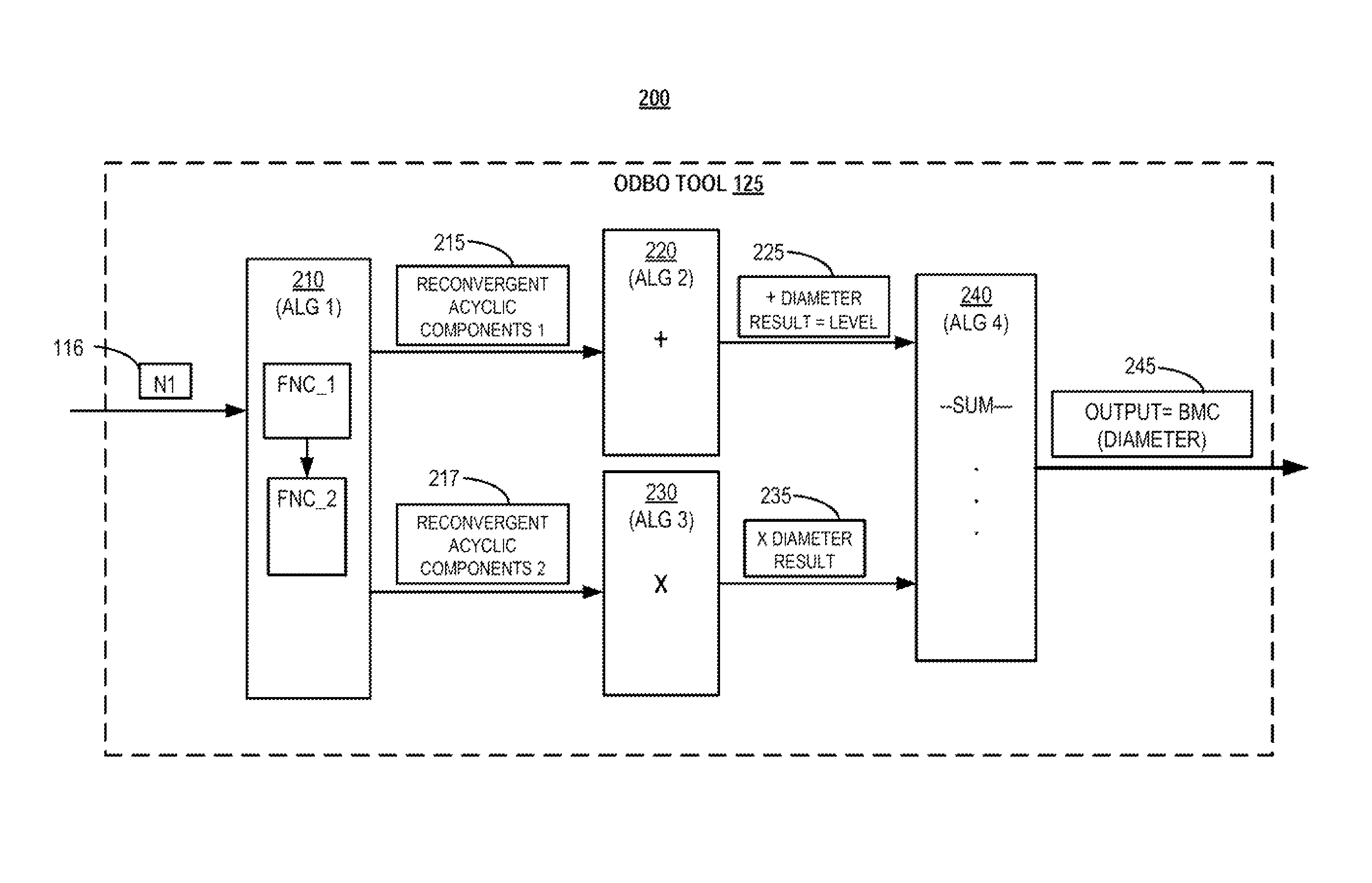
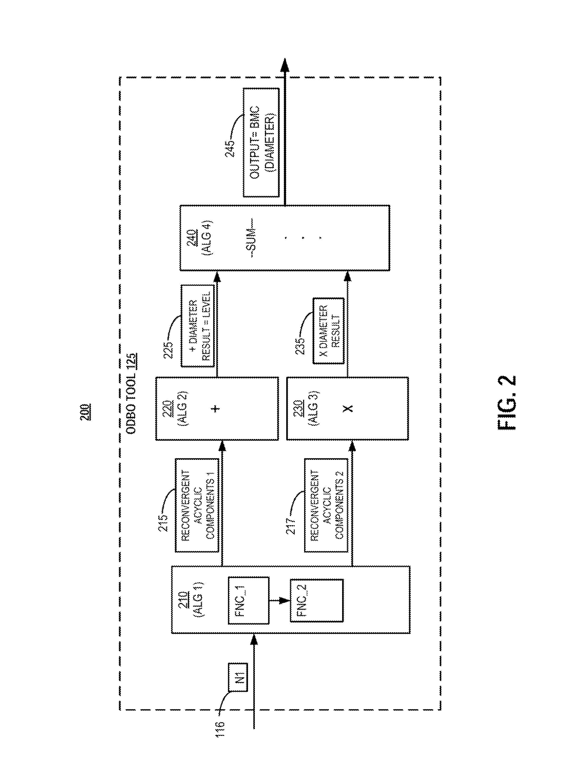
[0020]The illustrative embodiments provide a method, a computing device and a computer program product that implement a technique for determining a tight diameter bound over-approximation for logic designs with intricate and / or complex feed-forward components with reconvergent fanout of varying delay paths. Specifically, an embodiment of the disclosure provides a method for determining an optimal diameter bound for evaluating complex feed-forward components within a netlist. The method includes a processor identifying from a netlist one or more strongly connected component(s) within the netlist, where a strongly connected component is a component that can fan out to itself. The method includes identifying acyclic registers in two or more input paths to a first strongly connected component from a first input, wherein each path has a different propagation delay; computing an additive diameter bound for the first complex feed-forward component; and computing a multiplicative diameter b...


PUM


Abstract

A computer-implemented method includes a processor identifying, within the netlist, at least one strongly connected components (SCCs) that has a reconvergent fanin input with at least two input paths from the reconvergent fanin input having a different propagation delay to the SCC. The method then computes an additive diameter for the netlist comprising at least one SCC, where the additive diameter includes a fanin additive diameter determined based on a propagation delay difference of the at least two input paths to a SCC and a number of complex feed-forward components within at least one input path. In response to the reconvergent fanin input to the SCC providing a binate function, the method computes a multiplicative diameter for the SCC utilizing a least common multiple (LCM) derived from one or more propagation delay differences across each reconvergent fanin input leading to the SCC.

Description

BACKGROUND[0001]1. Technical Field[0002]The present disclosure generally relates to verification techniques for logic design and in particular to techniques for performing diameter bounding for complex feed-forward components in a logic design.[0003]2. Description of the Related Art[0004]Design verification refers to the process of establishing the correctness of a given logic design. Due to the complexity of modern logic designs, formal verification methods are gaining widespread use to augment the coverage shortcomings of simulation-based validation approaches. Formal verification methods are exhaustive, and thus are guaranteed to expose all possible logic flaws. In contrast, simulation-based validation is incomplete, and thus may fail to expose certain logic flaws (or bugs). While formal verification is a very powerful technology, formal verification generally requires exponential resources with respect to design size and thus is often only applicable to smaller design components...

Claims


Application Information

Patent Timeline
Patent Type & Authority Patents(United States)
IPC IPC(8): G06F17/50
CPCG06F17/5081G06F30/398
Inventor BAUMGARTNER, JASON R.CASE, MICHAEL L.KANZELMAN, ROBERT L.MONY, HARI
Owner GLOBALFOUNDRIES INC
Learn More