Locking quick release clamp assembly

a quick release and clamp assembly technology, applied in the field of firearms, can solve the problems of increased cost associated with such add-on enhancements, easy loss, non-uniform calibration and weapon sighting, etc., and achieve the effect of simple manufacturing and assembly, and reduced down time and operating costs

Active Publication Date: 2013-11-12
AMERICAN DEFENSE MFG
View PDF90 Cites 77 Cited by
  • Summary
  • Abstract
  • Description
  • Claims
  • Application Information

AI Technical Summary

Benefits of technology

[0028]In one aspect, the accessory may include a high-powered scope, night vision sight, or other sight or sighting accessory. The accessory sits on top of the gun barrel or the rail mount. The goal is to provide a quick-release mechanism that will not jam up when it gets dirty or is subject to extreme conditions such as hot or cold.
[0032]One preferred feature of the invention is to provide an apparatus that is ruggedized and reliable, thereby decreasing down time and operating costs. Another preferred feature of the invention is to provide an apparatus that has one or more of the characteristics discussed above but which is relatively simple to manufacture and assemble using a minimum of equipment.
[0033]According to another aspect of the invention, a system for mounting an accessory to a support structure is disclosed that includes a shaft having a longitudinal axis and a head portion. A lever is connected to the head portion of the shaft and is rotatable about an axis oriented in a crossing direction relative to the longitudinal axis of the shaft. A notch is formed in the head portion of the shaft and a lock, pivotably attached to the lever, is positioned to selectively interact with the notch so that the lock prevents rotation of the lever relative to the shaft when the lock is engaged with the notch.
[0035]Another aspect of the invention discloses a method of forming a quick release clamp assembly that includes connecting a first clamp member and a second clamp member with a shaft. A lever is engaged with the shaft so that the lever can be rotated to alter a distance between the first clamp member and the second clamp member. A button is attached to the lever so that it is movable relative to the lever and the shaft. The button is positioned on the lever so the button can prevent movement of the lever in a first direction when the button is engaged with a notch formed on the shaft.

Problems solved by technology

Such individualization increases the cost associated with such add-on enhancements.
Since the male portion of the Swan / Weaver rail is easily removed by the firearm operator, they are also easily lost and calibration and weapon sighting are difficult and nonuniform.
However, these rails, also, suffer from alignment problems due to the shock created by the gases and recoil energy generated during firing.
Some of the above devices suffer from a number of disadvantages.
First, conventional mounts are substantially cylindrical in cross-section, such that their bottom surface is curved, so they provide no stability if the weapon is leaned upon a wall, for example.
However, this structure makes it difficult to comfortably grip the weapon while holding the mount, and often places the user's hand in close proximity to the hot barrel during firing.
Thus, this location is often not optimal for users of different heights and different arm lengths.

Method used


Image

  • Locking quick release clamp assembly
  • Locking quick release clamp assembly
  • Locking quick release clamp assembly

Examples


Embodiment Construction

[0072]The present invention and the various features and advantageous details thereof are explained more fully with reference to the non-limiting embodiments described in detail in the following description.

1. System Overview

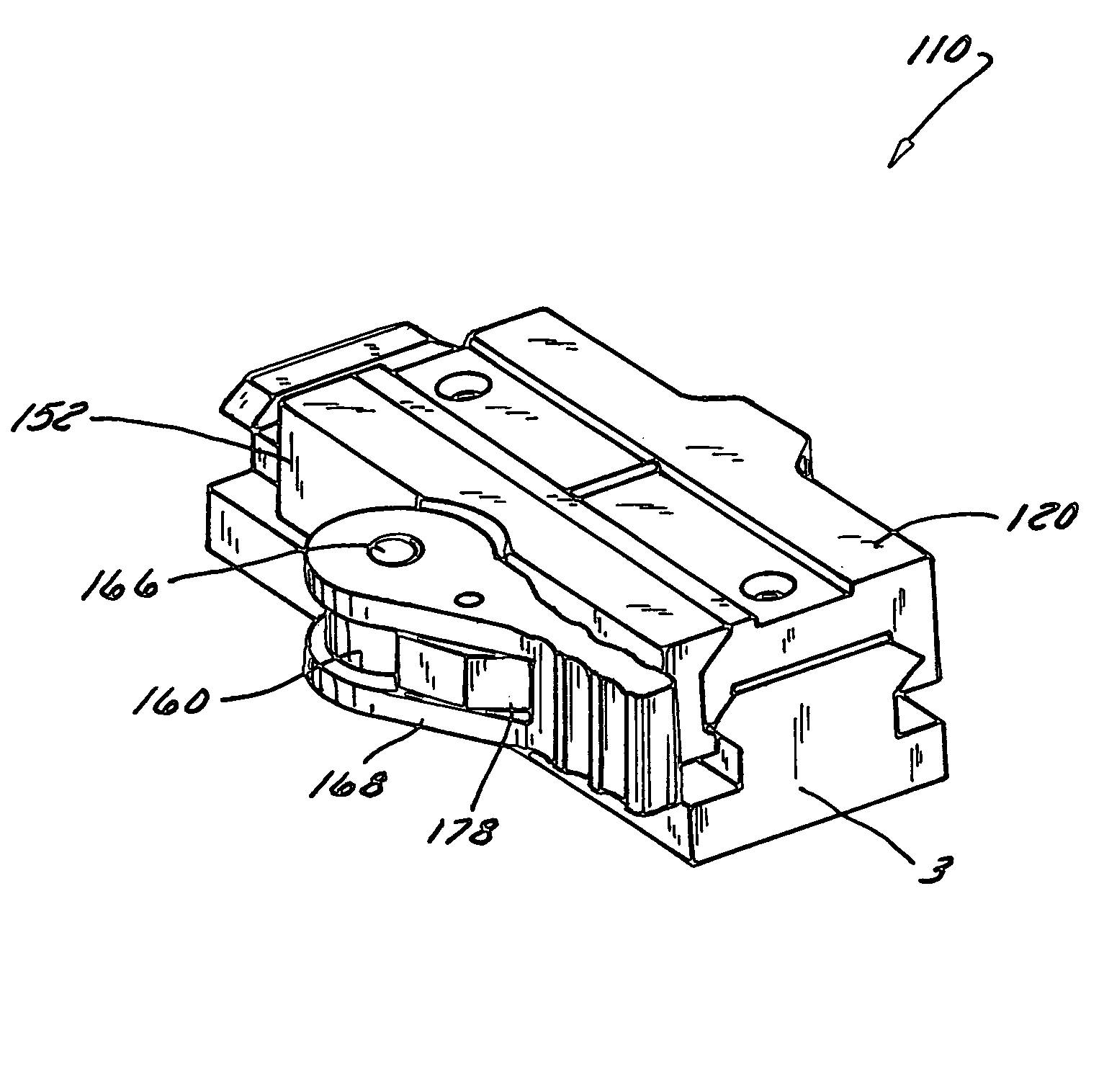
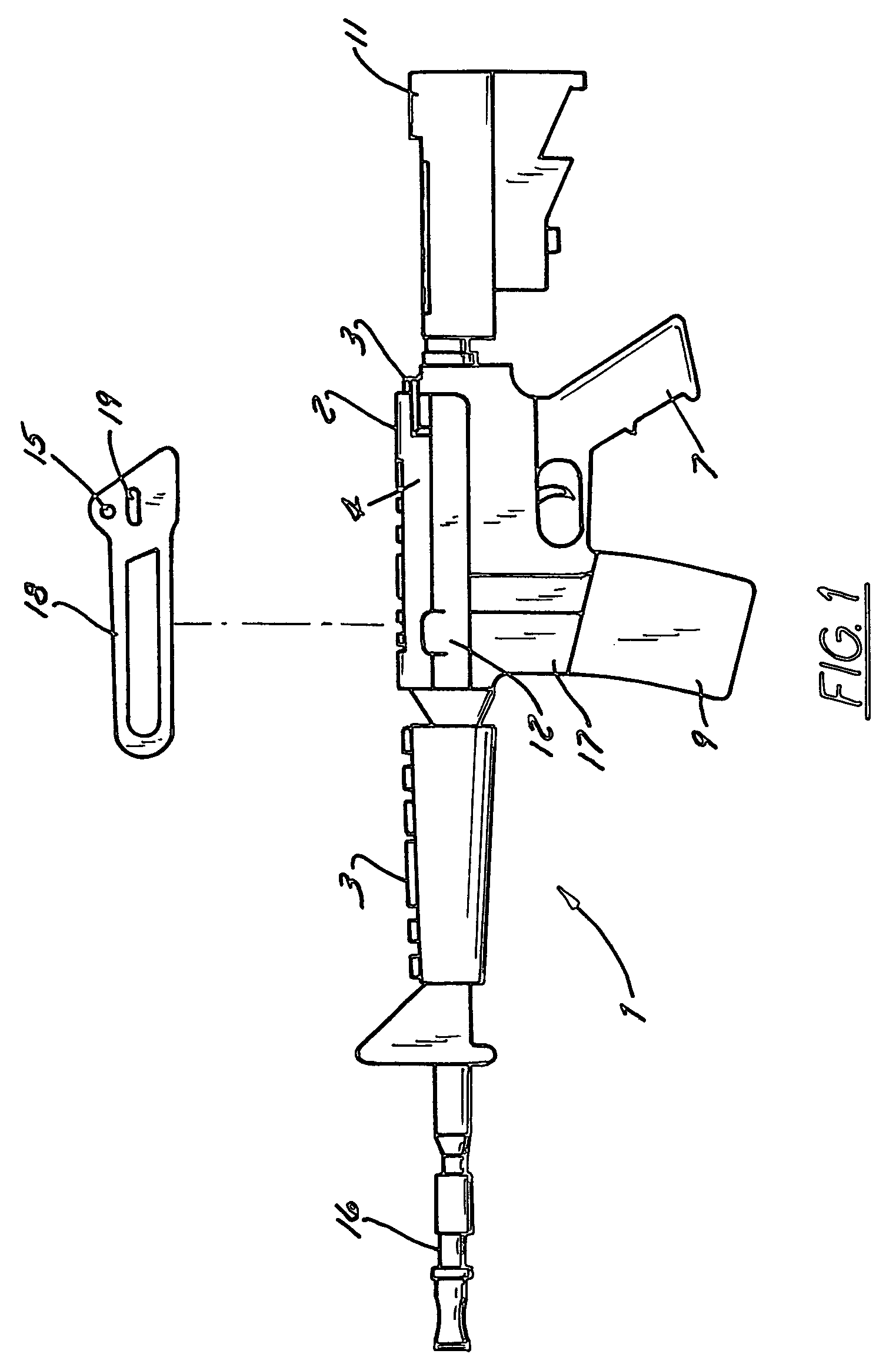
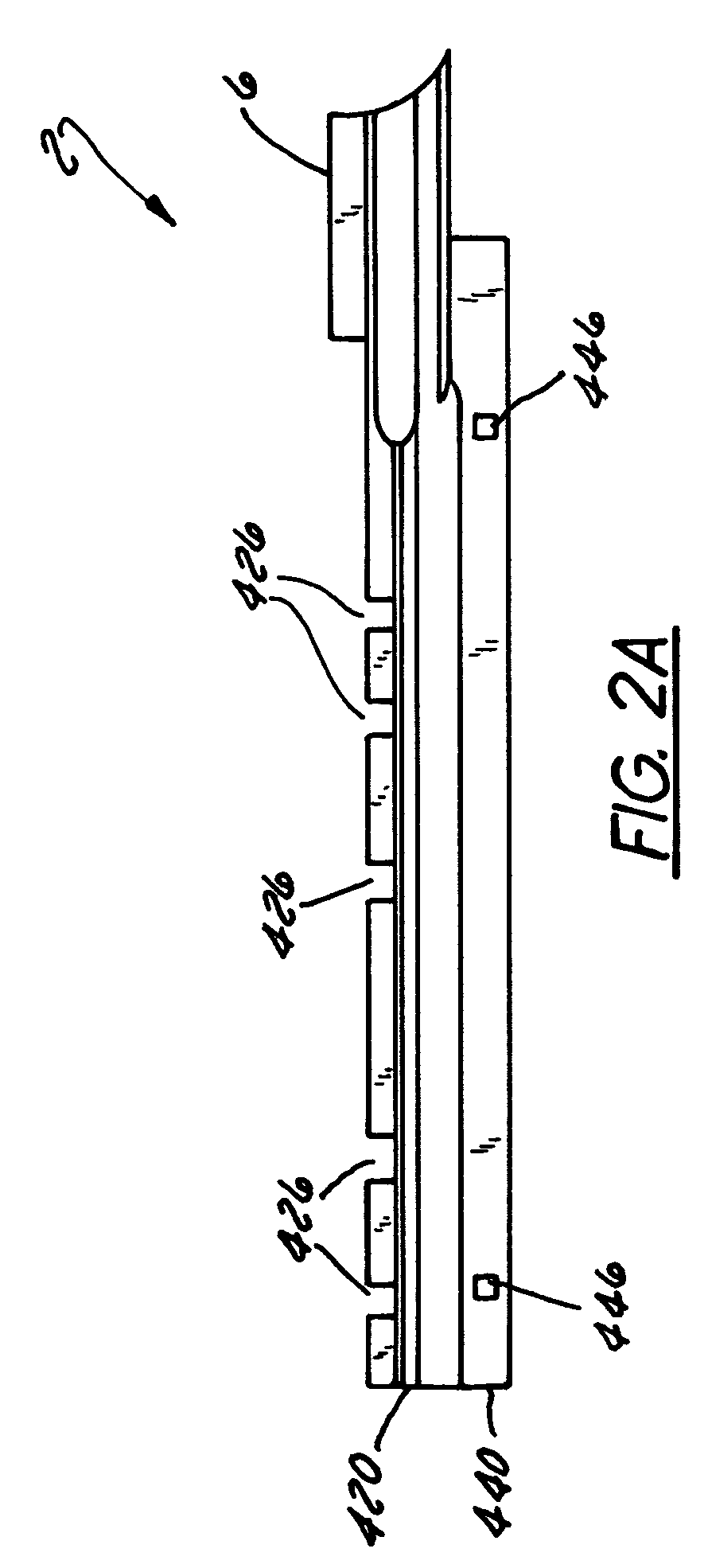
[0073]The invention solves the problem of having a locking mechanism that automatically locks the scope or other accessory onto a rail mount, rail system, or other underlying support. As tolerances of the rail or support may be off, the locking mechanism of the present invention may be adjusted without the use of specialized tools to maintain a constant tension and add durability. The locking mechanism includes a cam interface that defines a separation between facing structures and a lock that allows for only selective operation of the locking mechanism. In addition to firearm applications, it is appreciated that the locking mechanism can be used for securing any of a number of accessories in in-use or stored orientations relative to vehicles or other structures...


PUM

PropertyMeasurementUnit
transverse widthaaaaaaaaaa
widthaaaaaaaaaa
distanceaaaaaaaaaa

Abstract

Systems and methods for securely mounting devices and / or accessories to vehicles and / or other supporting structures. The systems include a shaft having a longitudinal axis. A pair of clamp bodies cooperates with the shaft so that a distance is defined between the clamp bodies. A lever is engaged with the shaft and operable to alter the distance between the clamp bodies. A lock supported by the lever movably engages the shaft and maintains the orientation of the clamp bodies relative to one another by maintaining an orientation of the lever relative to the shaft so that the lever can only be operated when the lock is disengaged from the shaft.

Description

CROSS-REFERENCE TO RELATED APPLICATIONS[0001]This application is a continuation in part and claims priority to U.S. patent application Ser. No. 12 / 024,619 filed on Feb. 1, 2008 now U.S. Pat. No. 7,823,316 and which claims the benefit of U.S. Patent Application Ser. Nos. 60 / 884,812, filed Jan. 12, 2007, and 11 / 959,020, filed Dec. 18, 2007, the disclosures of each of which are hereby incorporated in their entirety by reference.BACKGROUND OF THE INVENTION[0002]1. Field of the Invention[0003]The present invention relates in general to the field of firearms. More particularly, the present invention relates to a lockable quick release assembly that is useable in various contexts including gun mounts. Specifically, one embodiment of the present invention relates to a quick release-mounting device for a weapon. Another embodiment of the invention includes a lockable quick release assembly useable to secure one or more sporting accessories in a secure manner and in a manner wherein the acces...

Claims


Application Information

Patent Timeline
Patent Type & Authority Patents(United States)
IPC IPC(8): F41G1/38
CPCF41C27/00F41G1/387F41G11/003Y10T29/49826Y10T403/595
Inventor STORCH, TROYGROSS, JOHNORNE, III, WILLIAMKINCEL, ERIC STEPHEN
Owner AMERICAN DEFENSE MFG
Why Eureka
Try Eureka