Anti-noise panel

a technology of anti-noise and panel, which is applied in the direction of soundproofing, lamination, building components, etc., can solve the problems of not always suitable for a given application area, unsuitability of certain barriers currently in use, and inability to meet the construction features of noise barriers that are currently in use, etc., to achieve cost-effective, long-lasting, and effective noise reduction

Inactive Publication Date: 2013-11-12
ANGELICO MICHELE
View PDF21 Cites 18 Cited by
  • Summary
  • Abstract
  • Description
  • Claims
  • Application Information

AI Technical Summary

Benefits of technology

[0024]The characteristics and advantages of the present invention will be apparent from the detailed description reported below and the annexed Figures, wherein:

Problems solved by technology

The construction features of the noise barriers currently in use do not satisfy today's requirements.
Moreover, a great number of noise reduction solutions are produced with barriers that are very heavy and very expensive, but that nonetheless are not always suitable for a given area of application.
The unsuitability of certain barriers currently in use is due to the fact that several factors were considered marginal, or were not even taken into consideration, because they were not subjected to specific regulations until the new European Directives came into force.
Different types of materials are used in function to market requirements, however it is not always possible to satisfy both aesthetic and noise reduction requirements.
The barriers currently in use are easy to manufacture but with a low level of automation; the technologies are known and the materials are easy to obtain but are getting increasingly costly; some can be customized in order to blend into the surrounding environment but only within certain limits.
However, the barriers currently in use indeed have many disadvantages that can be summarized as follows:
They are extremely limited in terms of sound absorption efficiency as well as life cycle, which can be estimated at around 4 to 5 years; they require periodical maintenance; the installation is complicated and lengthy; the rock wool used is hazardous to health, and in fact is soon to be banned.
One of the main adverse point of said barriers is the fastening system because it must be specifically designed for each type of barrier.
Barriers currently in use are fitted into the cavity of the support structure but this is not sufficient to guarantee stability, therefore, bolts, anchors etc. are used on the side that does not face the noise source.
The said barriers are made of different pieces, therefore their stiffness is insufficient, and moreover the fastening elements must be secured manually and this entails additional manufacturing costs.
It is quite common to see a worker on a ladder or self-propelling platform carrying out maintenance, checking, tightening or replacing the fastening elements of barriers especially along railway lines where the compression wave generated by the passing of a train over time loosens the fastening elements, then often forces the barriers out of the support structure cavity and hurls them over the surrounding area, with all the risks entailed in the case of contact with persons because besides being heavy they also have sharp edges.
Disadvantages Regarding Maintenance Over Time:
In addition to the fact that barriers that use rock wool on the inside are soon to be banned (in view of the Directives EN 1793-1, ISO / R 354-1985 and DIN 52212), such barriers also have a limited life cycle.
Moreover, atmospheric conditions, and especially precipitation containing dust and pollutants seep into the rock wool causing deterioration of its physical / chemical properties and reducing its volume by more than 30%.
Said deterioration reduces the useful life of the barriers to 4-5 years; firstly there a loss of sound adsorption efficiency, and then the rock wool dust, which is very hazardous to health, is released into the atmosphere.
An additional disadvantage of the barriers currently in use regards their manufacturing process, which is not fully automated therefore the workers involved in the process are exposed to the dust that is continually released from the rock wool when it is fitted into the barriers.
Said barriers are open at the ends and have many perforations, thus any type of handling causes the release of rock wool dust into the air.
Another negative aspect of barriers currently in use concerns dismantling and disposal.
The fact that said barriers are made of metal parts that are very costly (steel or aluminum) implies the recovery of said parts, which is a very difficult and expensive process because it involves separating the metal from the rock wool, which must then be disposed off.

Method used


Image

  • Anti-noise panel
  • Anti-noise panel
  • Anti-noise panel

Examples


first embodiment

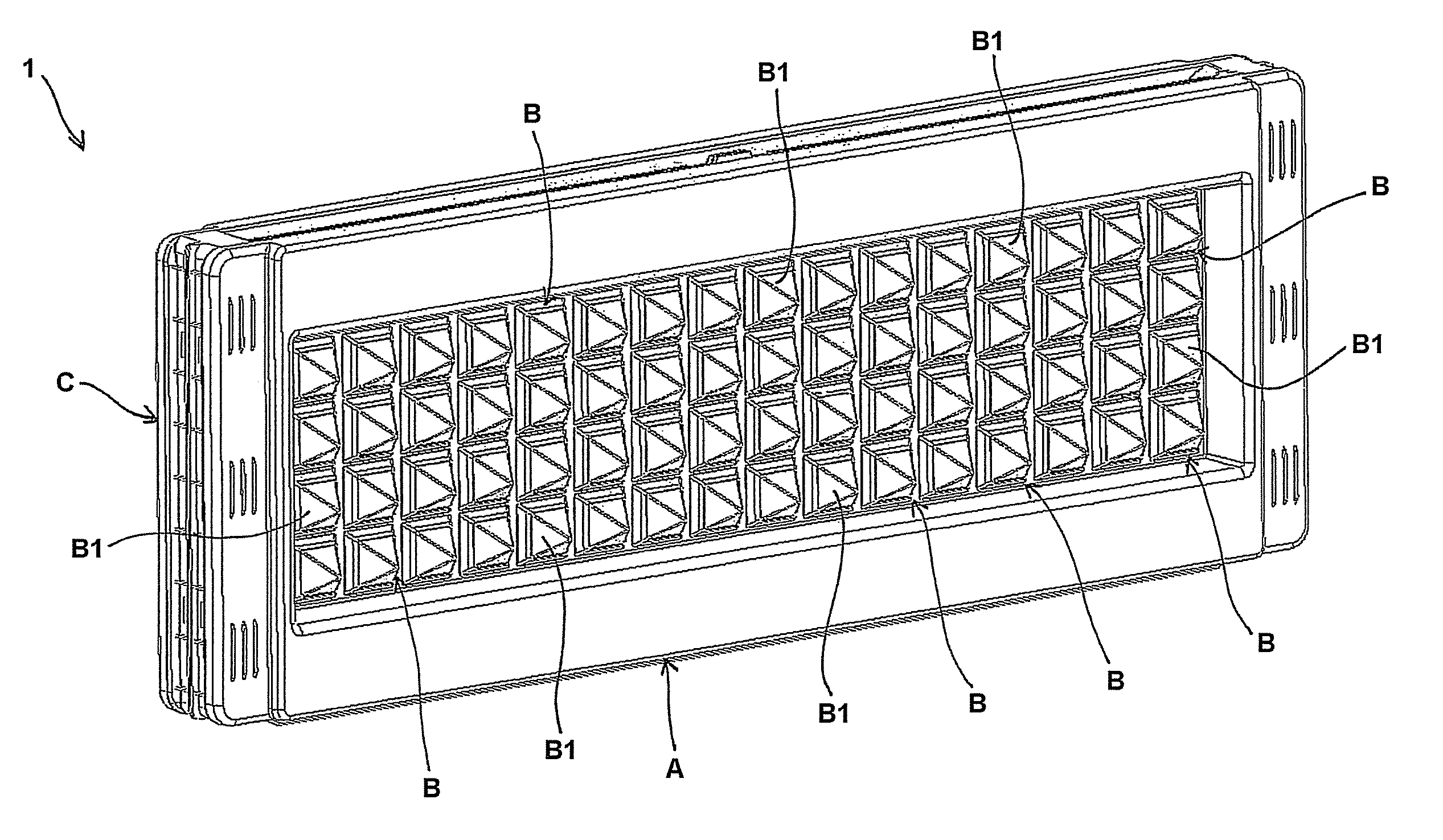
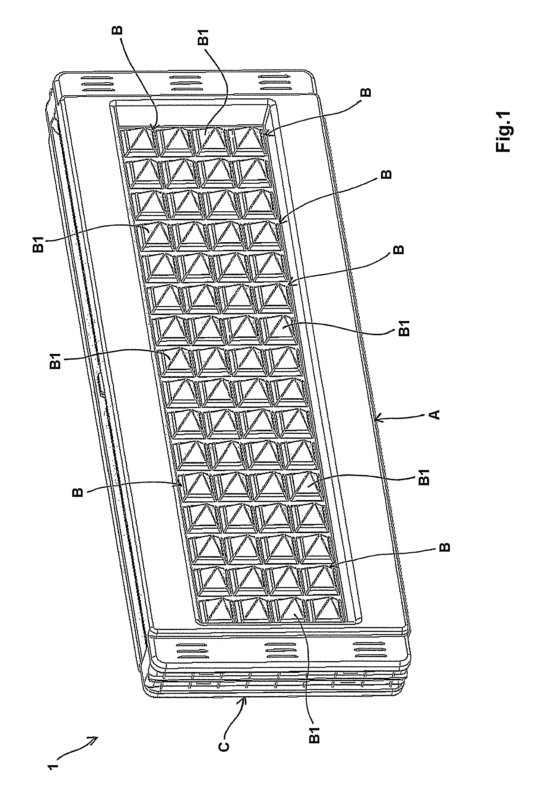
[0048]FIGS. 1 to 5 are relative to the anti-noise panel 1 according to the invention having a plurality of dampers. With reference in particular to FIGS. 1 and 2, the anti-noise panel 1 comprises a first plurality of dampers B on the said front shell A. Hereinafter this dampers B are also indicated with the expression “external dampers B” since they comprise an external part B1 which actually protrudes outwards of the sealed inner cavity IC. FIG. 1 and the section view of FIG. 4 show a preferred shape of these dampers B according to which the external part B1 has a pyramidal shape having a square base.

[0049]With reference in particular to the section view of FIG. 5, the external dampers B comprises also an internal part B2 which protrudes inwards of the inner cavity IC. The internal part B2 of the dampers B comprises lamellae 8 having different thickness and length that advantageously allow to absorb the energy deriving from sound waves of the relevant frequencies. In fact, said lam...

second embodiment

[0057]As illustrated in the section views of FIGS. 8 and 9, the configuration of the shells A, C in the second embodiment is substantially equivalent to that of the first one. Consequently, common elements relative to both embodiments are indicated in FIGS. 6-10 by using the same references used in the FIGS. 1-5. The one-piece structure of the anti-noise panel of the present invention and the successful sound absorption proved above allow to overcome the drawbacks of the prior art panels.

[0058]In a further aspect, the present invention relates to a process for manufacturing the anti-noise panel as above described, comprising the steps of

a) forming a front shell A, optionally incorporating at least one damper, by injection moulding,

b) forming a rear shell C, optionally incorporating at least one damper, by injection moulding, and

c) joining said front shell A to said rear shell C so that a sealed inner cavity is formed, thus obtaining the anti-noise panel.

[0059]The above process allow...


PUM

PropertyMeasurementUnit
frequenciesaaaaaaaaaa

Abstract

It is disclosed an anti-noise panel comprising a front shell and a rear shell that are coupled together within which rubber elements of specifically designed shape and size are incorporated. Said panel can be advantageously obtained by using also recycled, injected thermoplastic material, that allows the resulting panel to be conveniently used when the wind causes strong impact, for example, along railway lines where the compression waves generated by trains traveling at high speed over time tend to disassemble the riveted aluminum / steel sound barriers currently in use.

Description

FIELD OF THE INVENTION[0001]The present invention relates an anti-noise panel which can be used, for example, as a traffic noise barrier along roads, highways and / or railways. The panel according to the invention comprises a front shell and a rear shell, made of thermoplastic material, that are coupled together within which rubber elements of specifically designed shape and size are incorporated. Said panel can be advantageously obtained by using recycled, injected thermoplastic material, that allows the resulting panel to be conveniently used when the wind causes strong impact, for example, along railway lines where the compression waves generated by trains traveling at high speed over time tend to disassemble the riveted aluminum / steel sound barriers currently in use.STATE OF THE ART[0002]The construction features of the noise barriers currently in use do not satisfy today's requirements. Moreover, a great number of noise reduction solutions are produced with barriers that are ver...

Claims


Application Information

Patent Timeline
Patent Type & Authority Patents(United States)
IPC IPC(8): E04B1/82B32B37/00B29C65/00E04B2/02E04B1/84
CPCE01F8/0076E04B2001/8419E04B2001/8428E04B2001/8447E01F8/0023E01F8/0064E01F8/007E01F8/0082
Inventor ANGELICO, MICHELE
Owner ANGELICO MICHELE
Why Eureka
Try Eureka