

Clutch release mechanism and clutch assembly including same
a technology of release mechanism and clutch assembly, which is applied in the direction of friction clutches, interengaging clutches, and clutches, can solve the problems of poor workability, and achieve the effects of reducing the range of movement, reducing the deflection of pressing, and improving the stability of shifting feeling
- Summary
- Abstract
- Description
- Claims
- Application Information
AI Technical Summary
Benefits of technology
Problems solved by technology
Method used
Image

Examples
Embodiment Construction
[0033]It should be understood that only structures considered necessary for clarifying the present invention are described herein. Other conventional structures, and those of ancillary and auxiliary components of the system, will be known and understood by those skilled in the art.
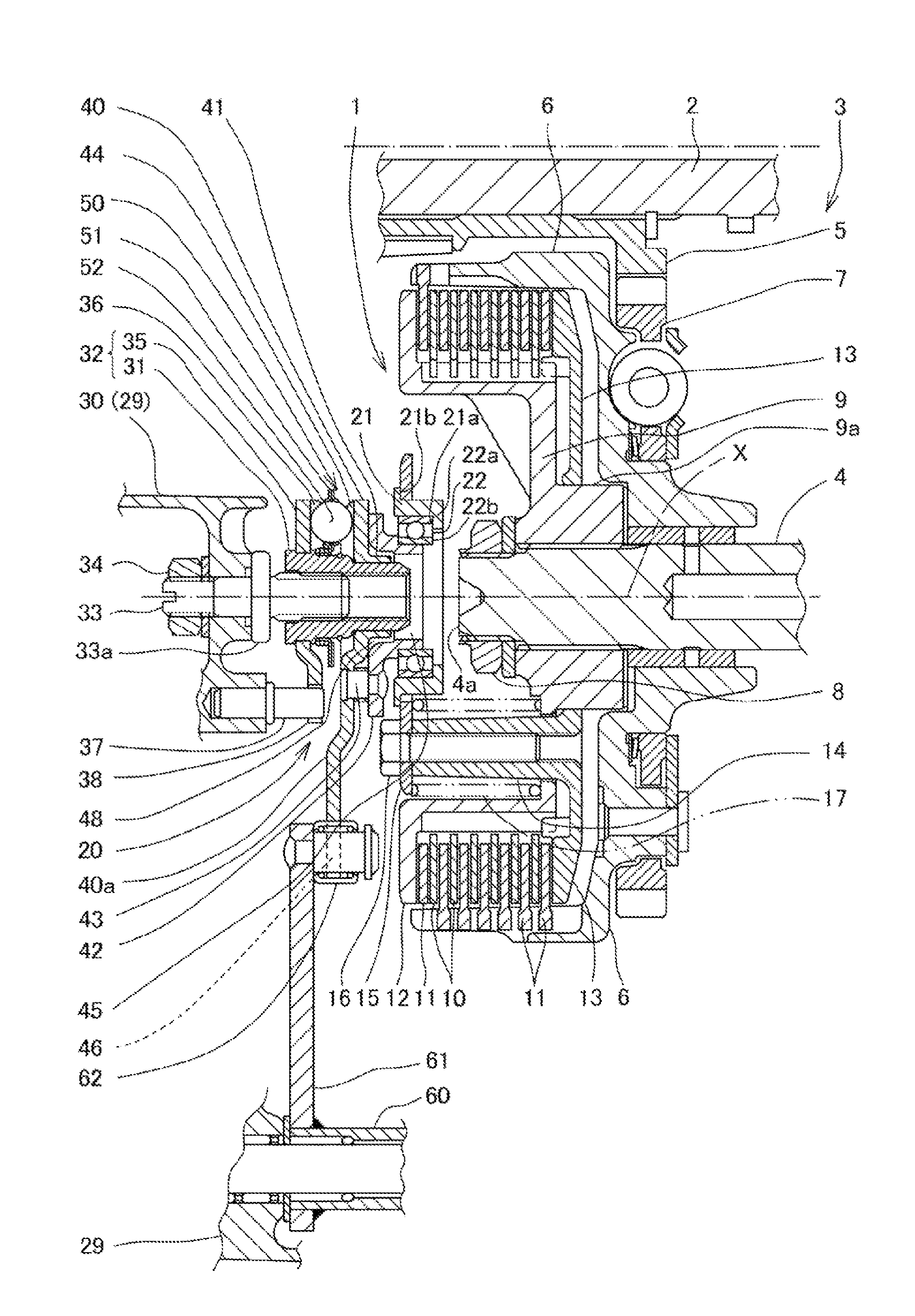
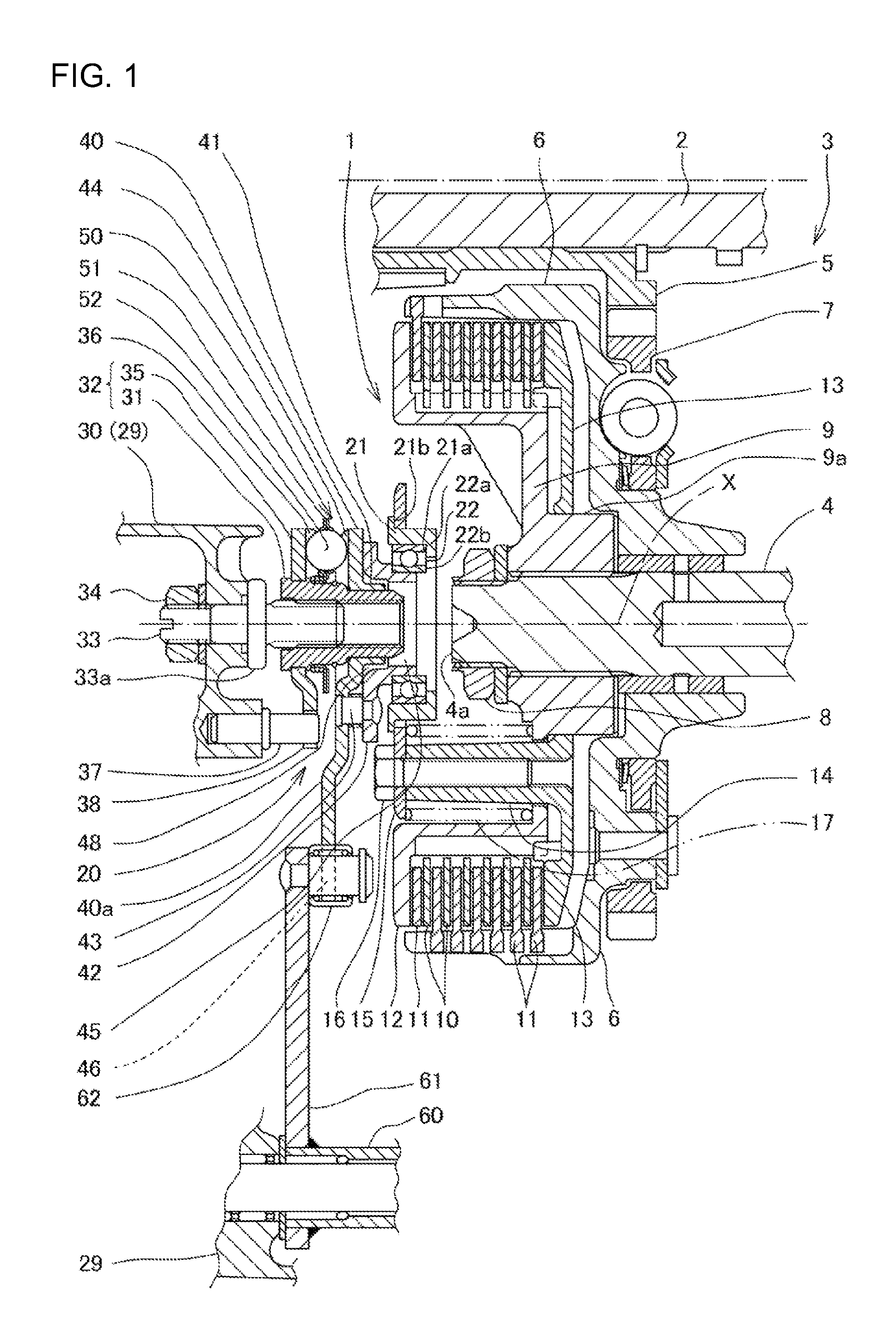
[0034]A clutch release mechanism according to a number of selected illustrative embodiments of the present invention, and a modification resulting from modifying part of the clutch release mechanism, will now be described with reference to FIGS. 1 through 5.
[0035]A clutch release mechanism 20, according to a first illustrative embodiment of the present invention described herein, is used to release the engagement of a multiple disk clutch device installed in a power unit of a motorcycle, an all-terrain vehicle or the like. However, the present invention shall not be limited to the use of a power unit in a vehicle. A clutch mechanism according to an embodiment of the present invention may also be applied to...
PUM
 Abstract
Description
Claims
Application Information