
Solenoid valve

a solenoid valve and valve cartridge technology, applied in the field of solenoid valves, can solve the problems of difficult removal of the solenoid valve valve cartridge with difficulty, and the advantage of the solenoid valve operating behavior, and achieve the effect of improving the flow properties of the armature chamber, easy to carry out, and easy to rinse out gas bubbles

Active Publication Date: 2013-11-12
ROBERT BOSCH GMBH
View PDF24 Cites 9 Cited by
  • Summary
  • Abstract
  • Description
  • Claims
  • Application Information

AI Technical Summary

Benefits of technology

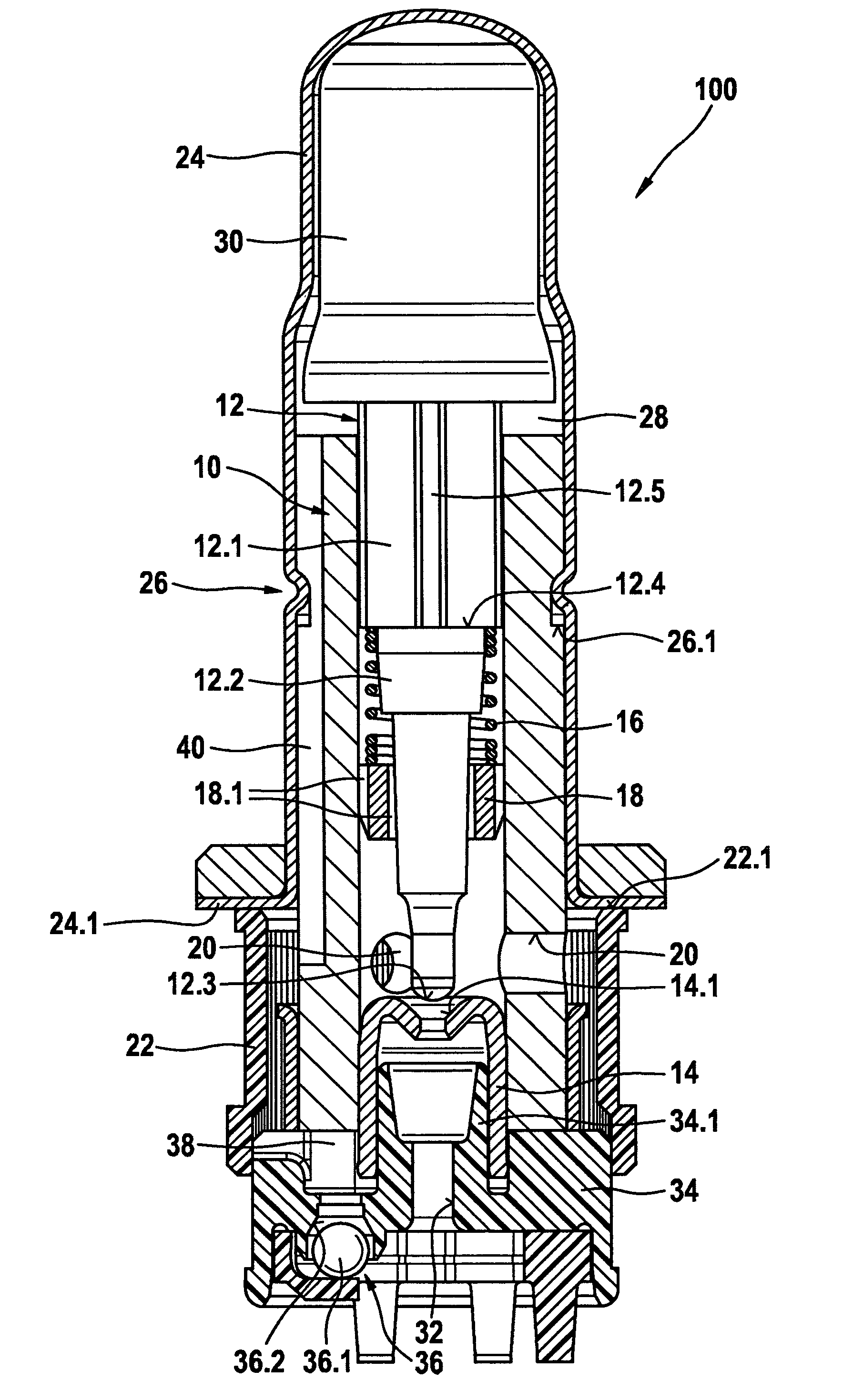
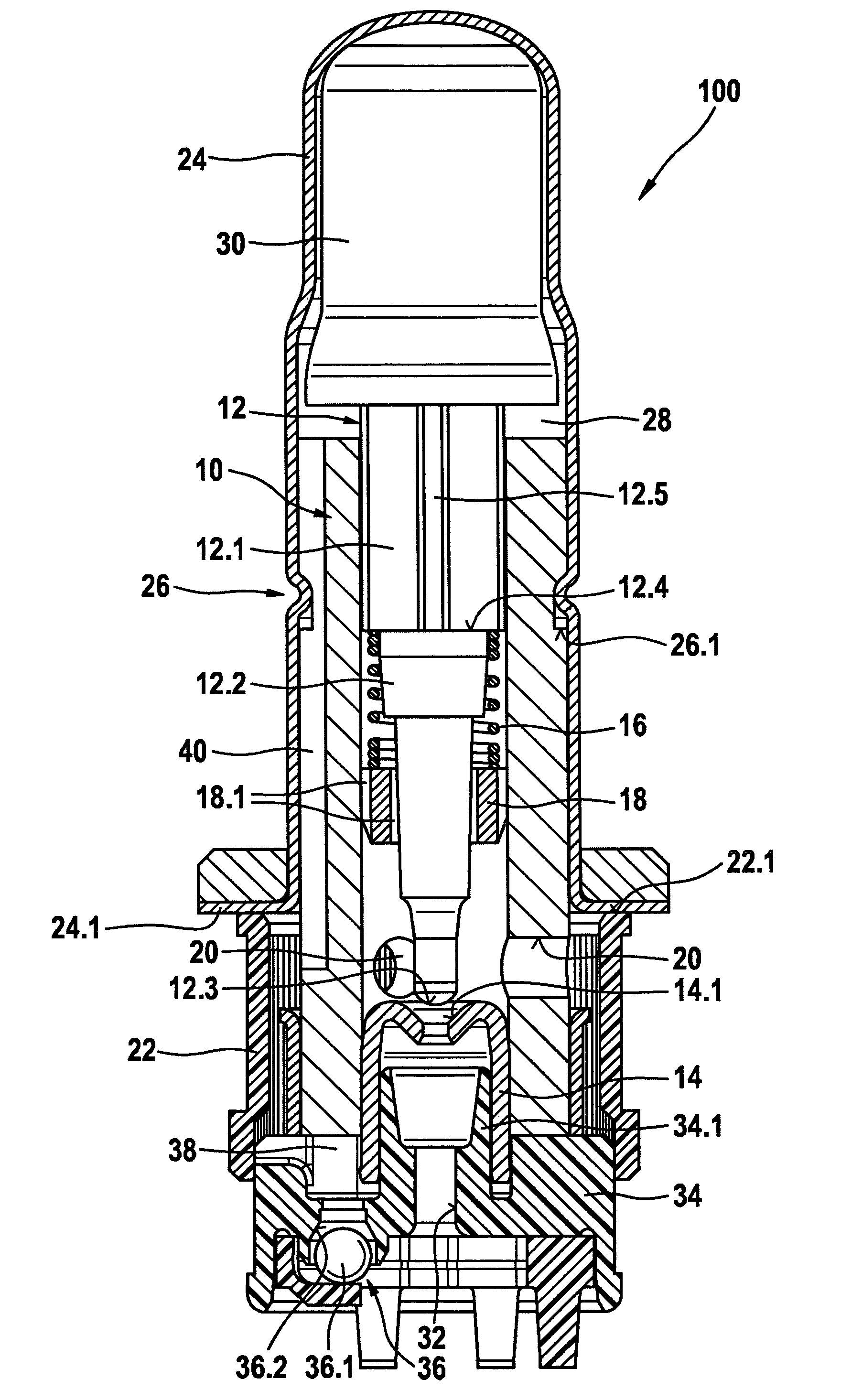
[0013]A solenoid valve according to the invention has the advantage over the prior art that an improvement in the armature chamber flow properties and thus in the removal of gas bubbles that may be present is achieved by means of design measures that are extremely easy to carry out. To accomplish this, in one proposal according to the invention, at least one second hydraulically effective connection of the armature chamber to the outlet, which is decoupled from the first hydraulically effective connection, is provided and is situated remote from the guide region for the tappet in the valve insert. Together with the above-described first hydraulic connection provided in the guide region for the tappet in the valve insert, this second hydraulically effective connection forms a closed flow path that extends from the inlet, through the valve element, via the guide region of the tappet in the armature chamber, and from the armature chamber, directly back to the outlet. It thus assures a flow through the armature chamber, making it relatively easy to rinse out gas bubbles that may be present. It is therefore possible to at least largely prevent the above-mentioned disadvantageous effects such as operating noise or a changed operating behavior of the solenoid valve.
[0014]The proposed second hydraulically effective connection can be implemented in a relatively simply designed and therefore inexpensive way by means of at least one longitudinal groove that is open toward the outside and extends from the outer circumference of the valve insert, along part of its axial length. The design of this longitudinal groove can be varied within wide latitudes with regard to its cross-sectional form (a cross-section in the form of a segment of a circle, a triangle, a rectangle, or a polygon) and / or with regard to its depth and can therefore be embodied in accordance with the valve and the function.

Problems solved by technology

Particularly with continuous control valves, gas bubbles can cause oscillations of the tappet, which are audibly perceptible in the form of noise and cause a disadvantageous change in the operating behavior of the solenoid valve.
Consequently, in solenoid valves according to the prior art, there is the risk that once the gas bubbles have collected in the armature chamber, they can only be removed from the valve cartridge of the solenoid valve with difficulty.

Method used


Image

  • Solenoid valve
  • Solenoid valve

Examples


Embodiment Construction

[0017]The valve cartridge 100 shown in the FIGURE has a valve insert 10 as one of its central components. This valve insert is a hollow, cylindrical component that is manufactured out of magnetically conductive material, for example by machining a block of solid material in a material-removing way or by rolling a sheet metal blank. A tappet 12 is guided in an axially moving fashion inside the valve insert 10. For this purpose, at one of its ends, the tappet 12 has a first guide section 12.1 whose outer dimensions are matched to the inner diameter of the valve insert 10. The guide section 12.1 protrudes partially from the terminal end of the valve insert 10. In the direction pointing into the interior of the valve insert 10, the guide section 12.1 is adjoined by a closure-member section 12.2. The latter extends in the form of a finger to the end of the tappet 12 remote from the guide section 12.1. It has several reductions in its outer diameter and it ends at a ball segment 12.3. Thi...


PUM


Abstract

The invention relates to a solenoid valve, particularly for controlling the brake pressure of a wheel brake of a slip-controllable hydraulic brake system of a motor vehicle. In known solenoid valves, there is a first hydraulically effective connection of an armature chamber of the solenoid valve to an outlet through the guide of a tappet in a valve insert. The first hydraulically effective connection ends in the form of a blind hole and thus does not permit flushing out gas bubbles which possibly have accumulated in the armature chamber. In order to solve this problem, the invention proposes a second hydraulically effective connection which is arranged away from the guide of the tappet, uncoupled from the first hydraulically effective connection. Thus, a closed pressure medium path is effected within a valve cartridge of the solenoid valve, the closed pressure medium path making possible an effective flushing of the armature chamber and thus a flushing out of gas bubbles.

Description

CROSS-REFERENCE TO RELATED APPLICATION[0001]This application is a 35 USC 371 application of PCT / EP 2009 / 061868 filed on Sep. 14, 2009.BACKGROUND OF THE INVENTION[0002]1. Field of the Invention[0003]The invention relates to a solenoid valve, in particular for controlling the brake pressure in a wheel brake of a slip-controllable hydraulic brake system of a motor vehicle.[0004]2. Description of the Prior Art[0005]Solenoid valves of this kind are already known, for example, from the applicant's prior patent application with the filing number DE 10 2007 053 134.8.[0006]In the following, slip-controllable hydraulic brake systems of motor vehicles are understood to be antilock brake systems (ABS), traction control systems (TCS), or electronic stability program systems (ESP). In these control systems, it is possible to use solenoid valves to control or regulate the brake pressure of at least one wheel brake, e.g. as a function of the slip ratios occurring in the respective wheel. These sol...

Claims


Application Information

Patent Timeline
Patent Type & Authority Patents(United States)
IPC IPC(8): F16K31/02F16K15/00F15B13/02E03B1/00F16K21/04F16K17/00
CPCB60T8/363F16K31/0665F16K31/0693Y10T137/87563B60T8/36F16K31/06F16K31/0606
Inventor AMBROSI, MASSIMILIANOHOUIS, NICOLASSCHUSTER, GERHARDHUBER, SIEGFRIEDSTOKMAIER, GERHARDBUCHENAU, INGOHILDEN, MICHAEL
Owner ROBERT BOSCH GMBH
Learn More