Microcatheter tip

a micro-catheter and tip technology, applied in the field of catheters, to achieve the effect of increasing flexibility and/or resilience, and difficult inserting into the patien

Active Publication Date: 2013-11-12
MERIT MEDICAL SYST INC
View PDF10 Cites 3 Cited by
  • Summary
  • Abstract
  • Description
  • Claims
  • Application Information

AI Technical Summary

Benefits of technology

[0009]The present invention is directed to a dilator having a stiffened shaft for use as part of an introducer sheath assembly. The dilator is typically utilized within a catheter sheath which is to be inserted into a patient. The catheter sheath typically comprises a somewhat resilient tubular member which can be difficult to insert into the patient. The dilator provides additional rigidity to allow for insertion of the catheter sheath into the vasculature or body cavity of a patient. The dilator can include a stiffener which extends from the proximal end of the dilator to the distal end of the dilator. A tip of the dilator extends distally to the dilator stiffener. The dilator tip has an increased degree of flexibility and / or resilience, which allows for insertion of the tip of the dilator into the patient in a manner that does not result in damage or unnecessary tearing of the patient's tissue.
[0010]According to one embodiment of the present invention, the transition between the stiffener and the tip of the dilator is positioned such that when the dilator is positioned within the catheter sheath, the transition is also positioned within the catheter sheath. In other words, a portion of the tip of the dilator is positioned inside the catheter sheath and a portion of the tip of the dilator is positioned outside the tip of the catheter sheath. By positioning the transition between the stiffener of the dilator and the tip of the dilator inside the catheter sheath, the catheter sheath can provide strain relief subsequent to lateral movement of the tip of the dilator in a manner that can reduce or prevent kinking of the dilator tip at the transition between the stiffener tip and the tip of the dilator. According to one embodiment of the present invention, the tip of the dilator is longer than traditional dilator tips allowing for positioning of the transition further back relative to the catheter sheath than known introducer sheath assemblies. In another embodiment, the catheter sheath is longer than traditional catheter sheaths such that the tip of the catheter sheath is positioned distally to the transition between the tip of the catheter and the catheter stiffener.
[0011]According to one embodiment of the present invention, the tip of the dilator is formed from a sleeve which is external to the stiffener tube and runs along the length of the stiffener tube. The sleeve extends an amount beyond the distal end of the stiffener providing a tip at the distal end of the dilator. According to one embodiment of the present invention, the tip of the dilator includes a flow back region which is in contact with the tip of the stiffener when a force is exerted against the end of the dilator tip. In this manner, contact surfaces are provided between the stiffener and the dilator tip providing additional strength to the tip portion of the sleeve in a manner that minimizes buckling of the sleeve.
[0012]According to one embodiment of the present invention, the dilator is manufactured by positioning the sleeve over the stiffener tube. A mandrel is positioned within the stiffener up to the distal end of the dilator, including the portion of the dilator corresponding with the tip portion of the sleeve. A die is also positioned along the length of the dilator adjacent the sleeve and / or the stiffener tube. A radio frequency or other heat source medium flows through the mandrel and die and is exerted on the sleeve and stiffener tube. Heating of the sleeve and stiffener tube forms the sleeve to the stiffening tube. Forming of the sleeve to the stiffening tube allows for proper operation of the dilator during the procedure for which the introducer sheath assembly is to be utilized.
[0014]According to one embodiment of the present invention, the dilator tip includes both a flow back portion or other contact surface to interface with the stiffener tube and a transition between the stiffener tube and the dilator tip which is positioned within the catheter sheath. By providing both a contact surface, a transition which can be positioned within the catheter sheath. Positioning of the transition in the catheter sheath provides a stronger, more reliable, and kink-resistant catheter tip.

Problems solved by technology

The catheter sheath typically comprises a somewhat resilient tubular member which can be difficult to insert into the patient.

Method used


Image

  • Microcatheter tip
  • Microcatheter tip
  • Microcatheter tip

Examples


Embodiment Construction

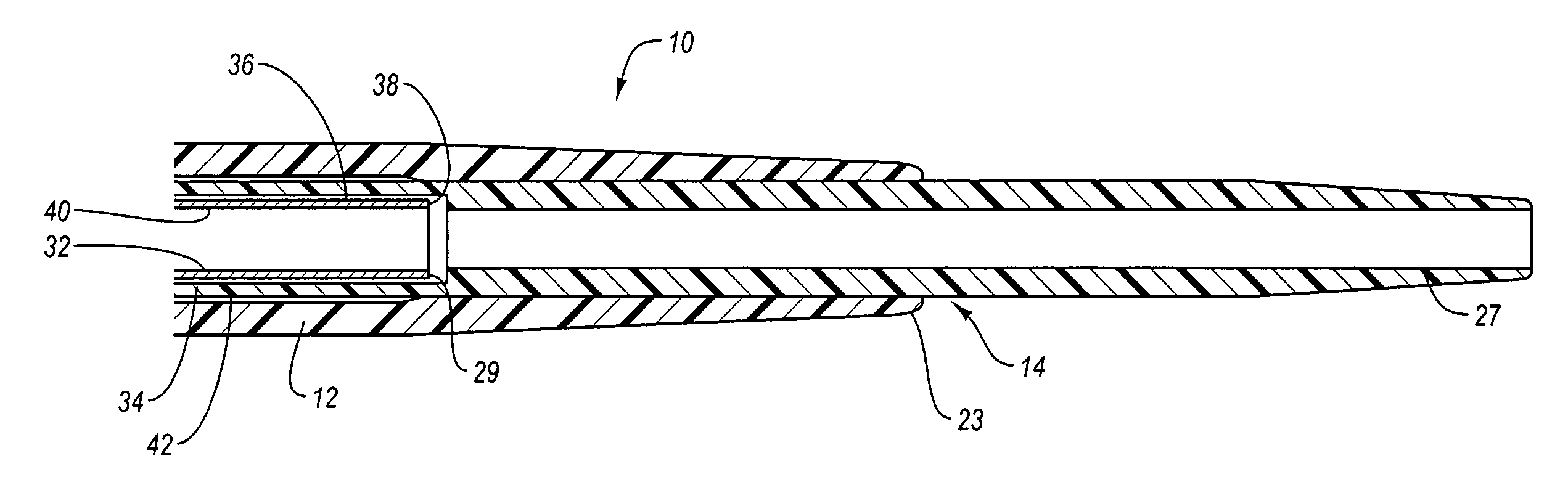
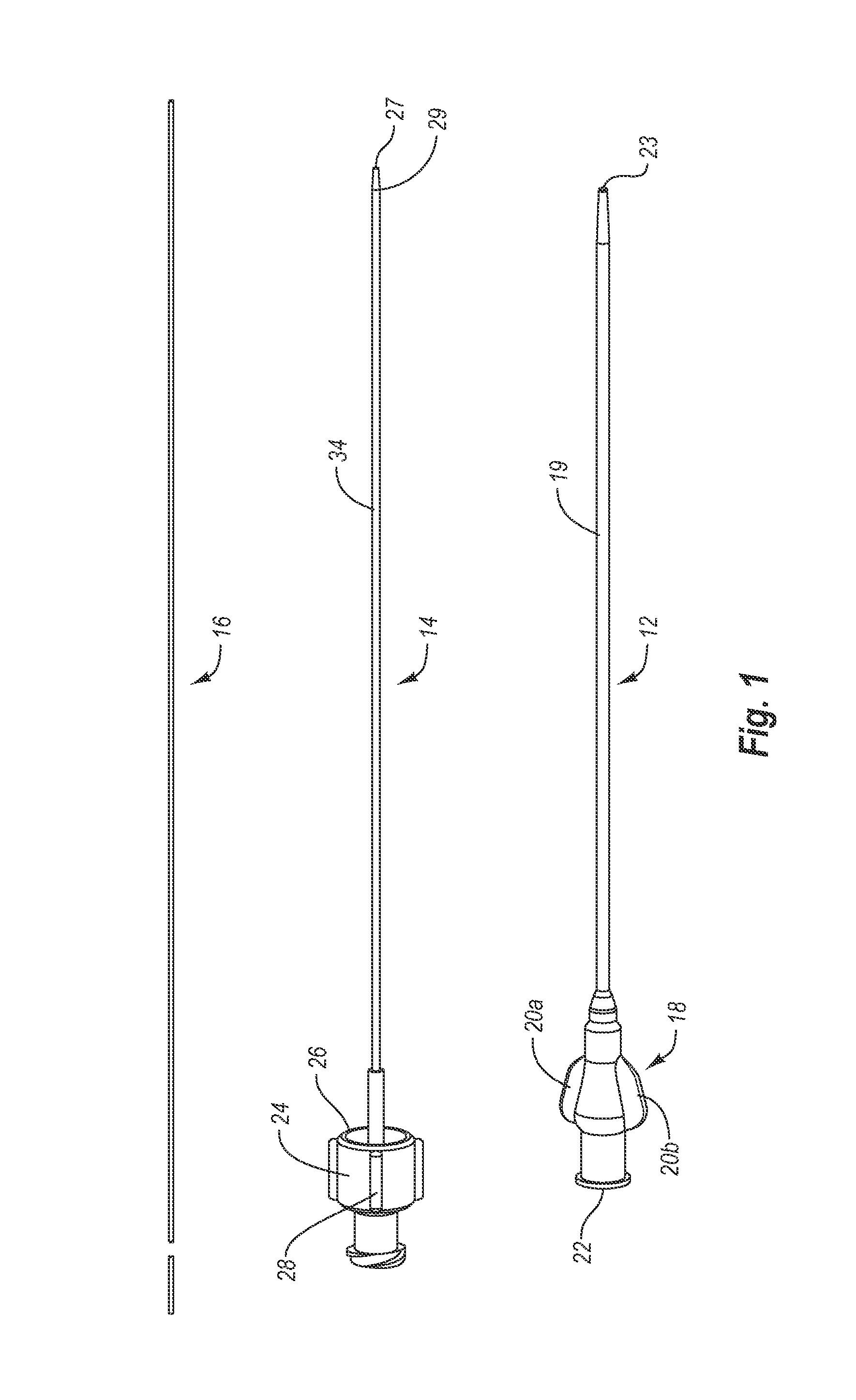
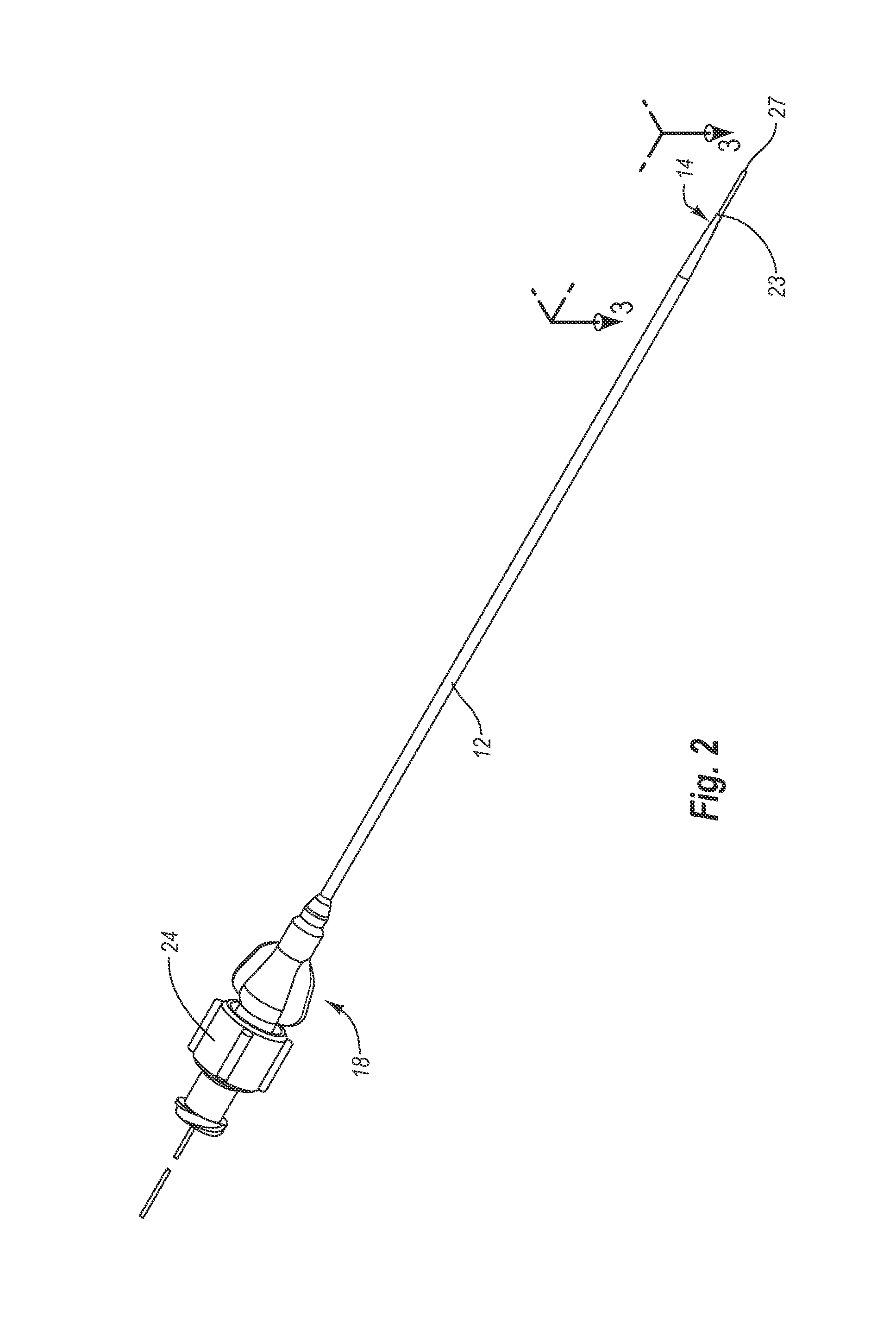
[0023]The present invention is directed to a dilator having a stiffened shaft for use as part of an introducer sheath assembly. The dilator is typically utilized within a catheter sheath which is to be inserted into a patient. The catheter sheath typically comprises a somewhat resilient tubular member which can be difficult to insert into the patient. The stiffened dilator provides additional rigidity to allow for insertion of the catheter sheath into the vasculature or body cavity of a patient. The stiffened dilator includes a stiffener which extends from the proximal end of the dilator shaft to the distal end of the dilator. A tip of the dilator extends distally to the stiffener tube. The dilator tip has an increased degree of flexibility and / or resilience, which allows for insertion of the tip of the dilator into the patient in a manner that does not result in damage or unnecessary tearing of the patient's tissue.

[0024]According to one embodiment of the present invention, the tra...


PUM

PropertyMeasurementUnit
rigidityaaaaaaaaaa
lengthaaaaaaaaaa
flexibleaaaaaaaaaa

Abstract

The present invention is directed to a dilator having a stiffened shaft for use as part of an introducer sheath assembly. The dilator includes a stiffener tube and a tip of the dilator which extends distally to the dilator stiffener tube. The transition between the stiffener tube and the tip of the dilator is positioned such that when the dilator is positioned within the catheter sheath, the transition is also positioned within the catheter sheath. By positioning the transition between the stiffener tube of the dilator and the tip of the dilator inside the catheter sheath, the catheter sheath can provide strain relief subsequent to lateral movement of the tip of the dilator in a manner that can prevent kinking of the dilator tip at the transition between the stiffener tip and the tip of the dilator.

Description

BACKGROUND OF THE INVENTION[0001]1. The Field of the Invention[0002]The present invention relates to catheters. In more particular, the present invention relates to an introducer sheath assembly having a reinforced dilator which minimizes kinking or bending of the dilator shaft.[0003]2. The Relevant Technology[0004]Catheters play an important role in the treatment and care of patients in modern medicine. In particular, catheters provide relatively unobtrusive access to remote portions of a patient's body, allowing desired procedures or treatments to be performed. A wide variety of generalized and specialized catheters have been developed and refined for particular uses. For example, angioplasty catheters have been adapted to provide a safe and effective conduit for the delivery of a stent and / or balloon to a narrowing or blockage in a patient's artery or vein. Typically, catheters are placed in a desired position within a patient utilizing a guidewire. The guidewire is threaded to t...

Claims


Application Information

Patent Timeline
Patent Type & Authority Patents(United States)
IPC IPC(8): A61B1/00
CPCA61M25/001A61M25/008A61M25/0068Y10T29/49826
Inventor ACCISANO, III, NICHOLAS GERALD
Owner MERIT MEDICAL SYST INC
Why Eureka
Try Eureka