
Projector with light-shielding member and holding member having varied coefficient of thermal conductivity

a technology of light shielding member and holding member, which is applied in the field of projectors, can solve the problems of thermal deformation of the drive gear, unstable rotation, and inability to rotate, and achieve the effect of high-efficiency control of the amount of ligh

Active Publication Date: 2013-11-19
SEIKO EPSON CORP
View PDF11 Cites 4 Cited by
  • Summary
  • Abstract
  • Description
  • Claims
  • Application Information

AI Technical Summary

Benefits of technology

The patent text describes a technology for controlling the amount of light from a projector. The technology uses a light-shielding member that is attached to a holding member and overcomes the problem of temperature rise when the light is shielded. By using a member with high thermal conductivity, the holding member is able to effectively shield the luminous flux and control the amount of light. The technology also restrains the temperature rise of the position changing unit where the light-shielding member is attached, ensuring stable operation. Overall, the technology improves image quality and allows for efficient control of light output from the projector.

Problems solved by technology

However, the light amount control device disclosed in JP-A-2007-71913 has a probability such that when the temperature rises in association with the shielding of the luminous flux by the shielding member, heat of the shielding member is transferred to the drive gear attached to the shielding member, and hence the drive gear is thermally deformed.
When the drive gear is deformed, the rotation may become unstable, or the rotation may be disabled.
Consequently, the shielding member cannot be changed in position with high degree of accuracy, so that adequate modulation of the amount of light may not be achieved by the light amount control device.

Method used


Image

  • Projector with light-shielding member and holding member having varied coefficient of thermal conductivity
  • Projector with light-shielding member and holding member having varied coefficient of thermal conductivity
  • Projector with light-shielding member and holding member having varied coefficient of thermal conductivity

Examples


first embodiment

[0033]Referring now to the drawings, a projector according to a first embodiment will be described.

[0034]The projector according to the first embodiment modulates a luminous flux emitted from a light source according to image data, forms an image light, and projects the image light onto a screen or the like in an enlarged scale.

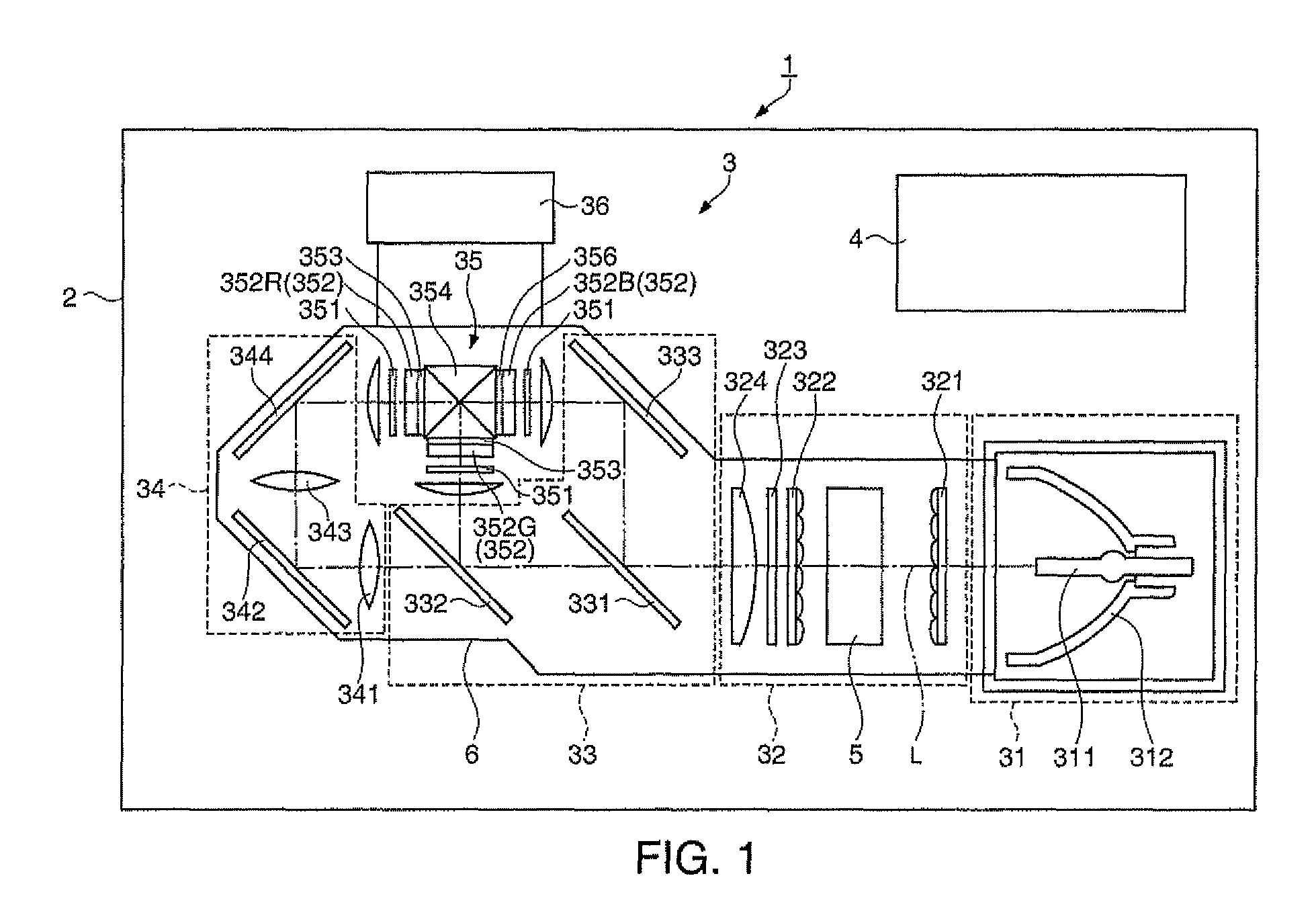
[0035]FIG. 1 is a diagrammatic drawing showing a schematic configuration of the projector according to the first embodiment.

[0036]As shown in FIG. 1, a projector 1 includes an outer housing 2, a control unit (not shown), an optical unit 3 having a light source 311, and a power source unit 4 configured to supply electric power to the light source 311 and the control unit. Although not illustrated, a cooling fan or the like configured to cool the interior of the projector 1 is arranged in the outer housing 2.

[0037]The control unit including a CPU (Central Processing Unit), a ROM (Read Only Memory), and a RAM (Random Access Memory) functions as a computer, and p...

second embodiment

[0112]Referring now to the drawings, a projector 1 according to a second embodiment will be described.

[0113]In the following description, like numbers reference like configurations and like members in the first embodiment, and detailed description will be omitted or simplified.

[0114]The projector 1 in the second embodiment has a pair of light-shielding member having different shape from the light-shielding members 81 and 91 in the first embodiment, respectively. The pair of light-shielding member is formed of a plate member of aluminum or the like in substantially symmetry with each other in the same manner as the light-shielding members 81 and 91, and are attached to the second gear 53 and the third gear 54 via the holding members 82 and 92.

[0115]Here, a light-shielding member 191 to be attached to the third gear 54 via the holding member 92 will be described with reference to the drawings.

[0116]FIG. 10 is a perspective view of the dimmer unit 9.

[0117]The light-shielding member 191...

third embodiment

[0124]Referring now to the drawings, a projector according to a third embodiment will be described.

[0125]In the following description, like numbers reference like configurations and like members in the first embodiment, and detailed description will be omitted or simplified.

[0126]The projector 1 in the third embodiment has a pair of light-shielding member having different shape from the light-shielding members 81 and 91 in the first embodiment, respectively. The pair of light-shielding member is formed of a plate member of aluminum or the like in substantially symmetry with each other in the same manner as the light-shielding members 81 and 91, and are attached to the second gear 53 and the third gear 54 via the holding members 82 and 92.

[0127]Here, a light-shielding member 291 to be attached to the third gear 54 via the holding member 92 will be described with reference to the drawings.

[0128]FIG. 11 is a cross-sectional view of the dimmer unit 9.

[0129]The light-shielding member 291...


PUM


Abstract

A projector includes: a light source, a light amount control device, an electro-optic unit, and a projection device, the light amount control device includes a light-shielding member configured to shield part of the luminous flux emitted from the light source, a holding member configured to hold the light-shielding member, the holding member is formed of a material having a coefficient of thermal conductivity lower than the coefficient of thermal conductivity of the light-shielding member, and a position changing unit configured to move or rotate in order to change the position of the light-shielding member, the light-shielding member is attached to the position changing unit via the holding member, and the light-shielding member comes into contact with the holding member via a projection provided on at least one of the light-shielding member and the holding member.

Description

BACKGROUND[0001]1. Technical Field[0002]The present invention relates to a projector configured to project an image light.[0003]2. Related Art[0004]In the related art, a projector configured to form an image light by modulating a luminous flux emitted from a light source according to image data, and project the image light onto a screen or the like. The projector is used in various applications such as presentations in companies or appreciation of movies in the family. In order to improve a contrast of an image, a technique to control amount of light of the luminous flux emitted from the light source using a light amount control device is proposed (see JP-A-2007-71913).[0005]The light amount control device disclosed in JP-A-2007-71913 includes a rectangular tubular shaped fixing member, a supporting shaft (axis of rotation) attached to the fixing member, a shielding member configured to partly shield the luminous flux emitted from the light source, a drive gear, a motor having a pin...

Claims


Application Information

Patent Timeline
Patent Type & Authority Patents(United States)
IPC IPC(8): G03B21/14G03B21/18G02B26/02G02B9/08G03B21/22G03B21/26G02B9/00
CPCG03B21/14G03B21/16G03B21/208
Inventor NAKANO, HIROHISA
Owner SEIKO EPSON CORP
Learn More