Ferrule with alignment pin channels

a technology of alignment pins and ferrules, applied in the field offerrules, can solve the problems of significant losses, interference between the mating ferrules and the alignment pins, affecting the alignment of the fiber core, etc., and achieves the effects of improving optical performance, reducing stress, and close toleran

Active Publication Date: 2013-11-19
TE CONNECTIVITY NEDERLAND
View PDF8 Cites 14 Cited by
  • Summary
  • Abstract
  • Description
  • Claims
  • Application Information

AI Technical Summary

Benefits of technology

[0011]The present invention provides a ferrule that has improved optical performance by relieving stress between the alignment guide pins. Specifically, Applicants discovered that the close tolerance of the distance between the alignment pins often results in interference between the mating ferrules and the alignment pins during mating. As force is applied to mate the ferrules, the alignment pins and the ferrule around the alignment pins deforms, creating stress in the mated ferrules. This deformation and stress, in turn, affects the ferrules' alignment, ultimately affecting the alignment of the fiber cores. This is particularly problematic in single mode applications in which the core diameter is only nine microns. Thus even slight movement of the mating fiber cores relative to each other results in significant losses. Additionally, depending on how the ferrules were mated and where the stresses were concentrated, different optical fibers along the ferrule end face would be affected differently. Therefore, optical performance among the fibers would vary each time the ferrules were mated. Furthermore, because the pins and ferrule are stressed, during temperature cycling, when their modulus changes, the stress actually induces movement of the pins / ferrule relative to each, thereby further affecting optical performance. This is evidenced in FIG. 5 in the dramatic change in attenuation during the initial temperatures cycle.
[0012]To solve this problem, Applicants recognize that certain tolerances of the MT ferrule can be relaxed to avoid stress yet not compromise optical performance. In particular, Applicants recognized that the close tolerance between the alignment pin channels (e.g., 4.6±0.003 mm for MT MPO ferrules) is not necessary. Rather, all that is needed for fiber core alignment is a single alignment pin channel against which the fiber channels can be registered, and a second alignment pin channel to prevent angular misalignment of the ferrules. Accordingly, the ferrule of the present invention has one alignment pin channel that is closely toleranced around the alignment pin in two dimensions, thus providing a price location on the ferrule end face against which the fiber channels can be registered. The other alignment pin channel is closely toleranced only in one dimension to prevent angular misalignment of the ferrules. The other dimension is left loose to allow movement of the alignment pin and thus avoid stress.
[0013]This approach has a number of advantages. First, as mentioned above, it reduces the stress between the alignment pins and thereby improves the repeatability of the optical performance for the mated ferrules. Additionally, it is anticipated that, since only one alignment pin is used to register the fiber channels, the registration of the channels to this alignment pin channel will improved over time. Another benefit is that the molding processes is simplified as only one alignment pin channel needs to be closely toleranced in both dimensions. Still other advantages will be apparent to those of skill in the art in light of this disclosure.

Problems solved by technology

Specifically, Applicants discovered that the close tolerance of the distance between the alignment pins often results in interference between the mating ferrules and the alignment pins during mating.
This deformation and stress, in turn, affects the ferrules' alignment, ultimately affecting the alignment of the fiber cores.
This is particularly problematic in single mode applications in which the core diameter is only nine microns.
Thus even slight movement of the mating fiber cores relative to each other results in significant losses.
Furthermore, because the pins and ferrule are stressed, during temperature cycling, when their modulus changes, the stress actually induces movement of the pins / ferrule relative to each, thereby further affecting optical performance.

Method used


Image

  • Ferrule with alignment pin channels
  • Ferrule with alignment pin channels
  • Ferrule with alignment pin channels

Examples


Embodiment Construction

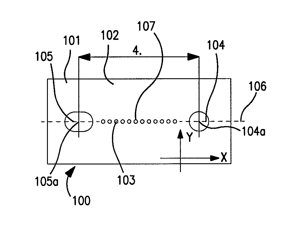
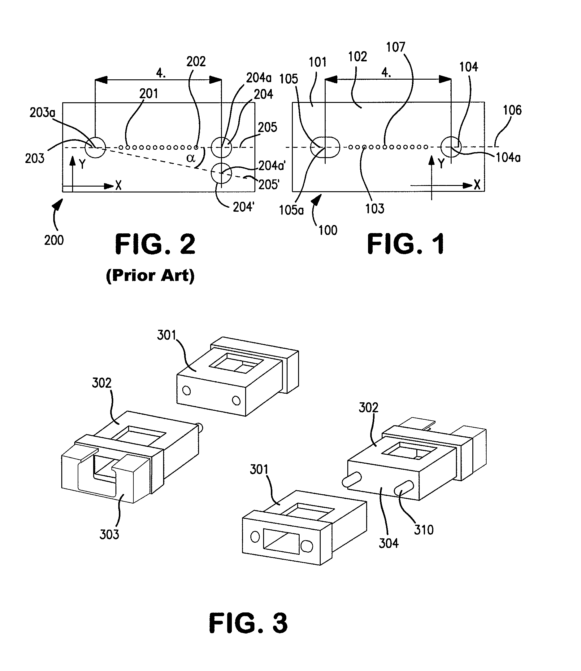
[0021]Referring to FIG. 1, one embodiment of the ferrule 100 of the present invention is shown. The ferrule 100 comprises a body 101 defining an end face 102. One or more channels 103 extend from the end face 102 through the body 101. Each channel 103 is adapted to receive an optical fiber (not shown). The ferrule body also defies first and second alignment pin channels, 104, 105. Each alignment pin channel has a center point 104a, 105a, which are disposed along a first axis 106 (dotted line). The first alignment pin channel 104 has a first cross section essentially the same as that of an alignment pin 310 (see FIG. 3), and is adapted to receive the alignment pin. The second alignment pin channel 105 has a second cross section elongated along the first axis 106. Each of the elements is considered below in detail and with respect to alternative embodiments.

[0022]The body 101 of the ferrule serves to define the fiber channels 103 and the alignment pin channels 104, 105 and is suitable...


PUM


Abstract

An optical ferrule comprising: (a) a body defining an end face; (b) one or more channels extending from said end face through said body, each channel adapted to receive an optical fiber; and (c) first and second alignment pin channels defined in said end face, each alignment pin channel having a center point, said center points being disposed along a first axis, said first alignment pin channel having a first cross section essentially the same as that of an alignment pin and being adapted to receive said alignment pin, said second alignment pin channel having a second cross section elongated along said first axis.

Description

FIELD OF INVENTION[0001]The present invention relates generally to ferrules for optical connectors, and, more specifically, to MT ferrules.BACKGROUND[0002]Optical fiber connectors are an essential part of substantially any optical fiber communication system. For instance, such connectors are used to join segments of fiber together, to connect fiber to active devices such as radiation sources, detectors and repeaters, and to connect fiber to passive devices, such as switches, multiplexers, and attenuators.[0003]A typical optical fiber connector comprises housing and a ferrule assembly within the housing. The ferrule assembly comprises a ferrule, which has one or more fiber channels to accommodate fibers, and a fiber secured in each channel such that the end of the fiber is presented for optical coupling by the ferrule. The housing is designed to engage a “mating structure” having an optical path to which the fiber optically couples during mating. The mating structure may be another c...

Claims


Application Information

Patent Timeline
Patent Type & Authority Patents(United States)
IPC IPC(8): G02B6/36
CPCG02B6/00G02B6/3885
Inventor BUIJS, MARCELLUS P. J.DUIS, JEROEN ANTONIUS MARIARIETVELD, JAN WILLEMBOLHAAR, ANTONIUS BERNARDUS GERARDUSSCHNEIDER, PAULVOS, JOSEPH GERARDUS MARIAELENBAAS, JACCO
Owner TE CONNECTIVITY NEDERLAND
Why Eureka
Try Eureka