Valved catheter with power injection bypass

a technology of bypass valve and valve catheter, which is applied in the direction of valves, intravenous devices, other medical devices, etc., can solve the problems of impracticality and danger of inserting and removing, and the treatment of chronic disease often requires repeated and prolonged access to the vascular system

Inactive Publication Date: 2013-11-19
NAVILYST MEDICAL
View PDF195 Cites 80 Cited by
  • Summary
  • Abstract
  • Description
  • Claims
  • Application Information

AI Technical Summary

Benefits of technology

[0003]In one aspect, the present invention is directed to a valve assembly for a catheter comprising a housing having a lumen extending therethrough a first port opening to a proximal end of the lumen via a first port passage and a valve disposed in the first port passage, the valve being biased toward a closed configuration to prevent fluid flow therethrough when the first port passage is not in use in combination with a second port opening of the housing in fluid connection with a proximal end of the lumen via a second port passage, the second port passage opening to the lumen distally of the safety valve.

Problems solved by technology

The treatment of chronic disease often requires repeated and prolonged access to the vascular system.
As it is impractical and dangerous to insert and remove a catheter at every session, patients are often fitted with a semi-permanent catheter which is left in place for months or years.

Method used


Image

  • Valved catheter with power injection bypass
  • Valved catheter with power injection bypass
  • Valved catheter with power injection bypass

Examples


Embodiment Construction

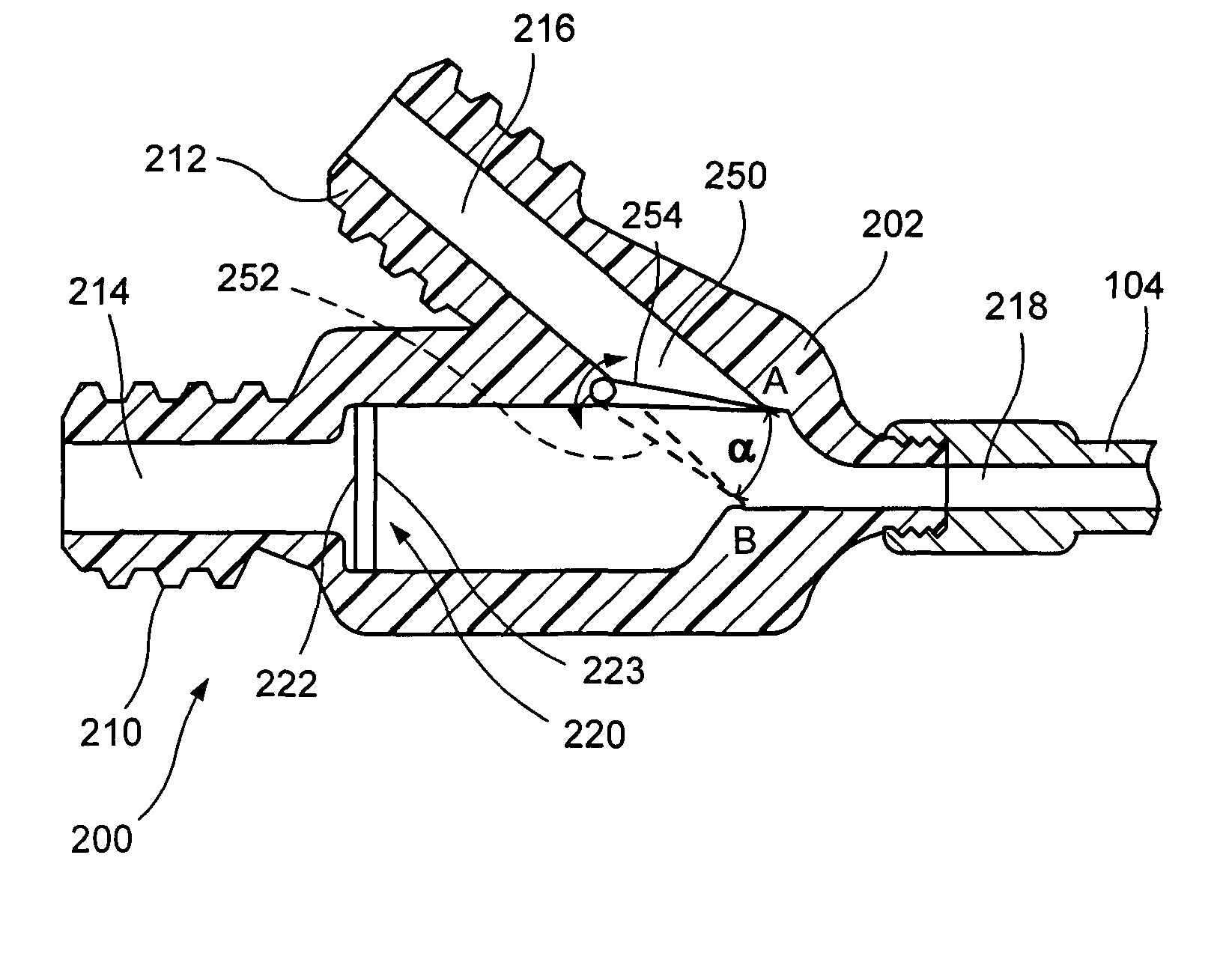
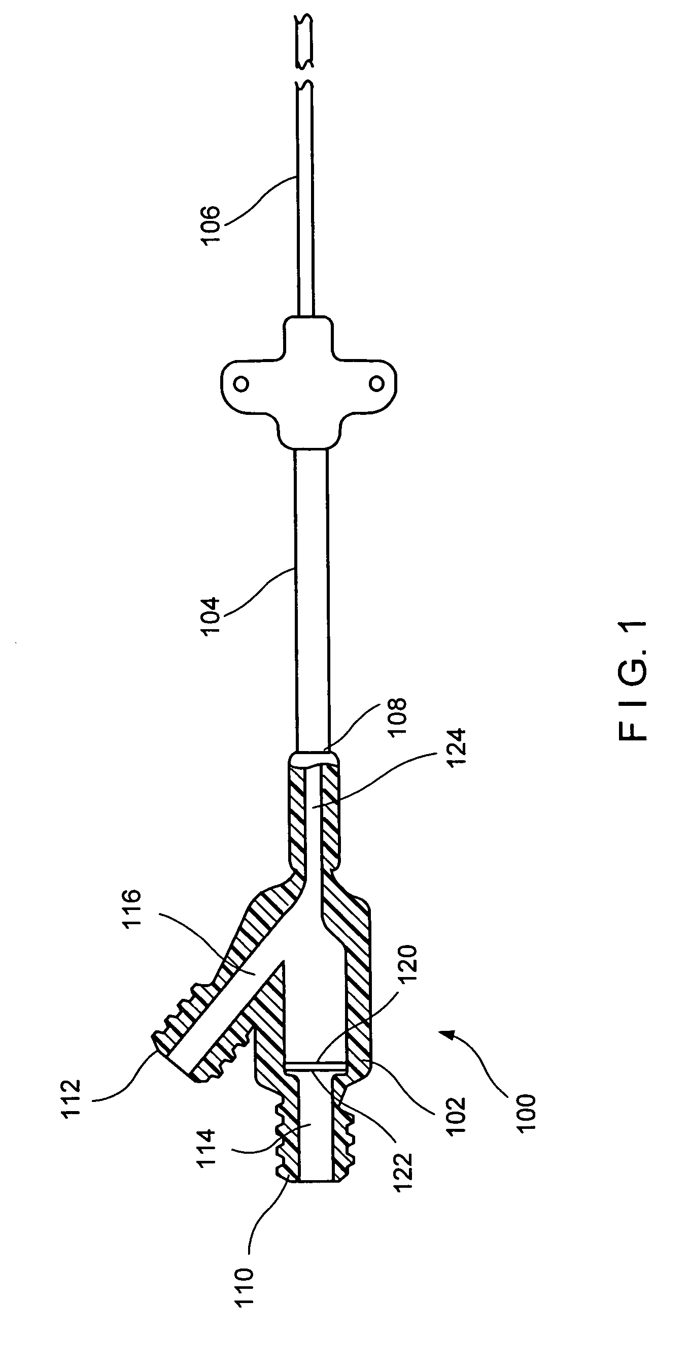
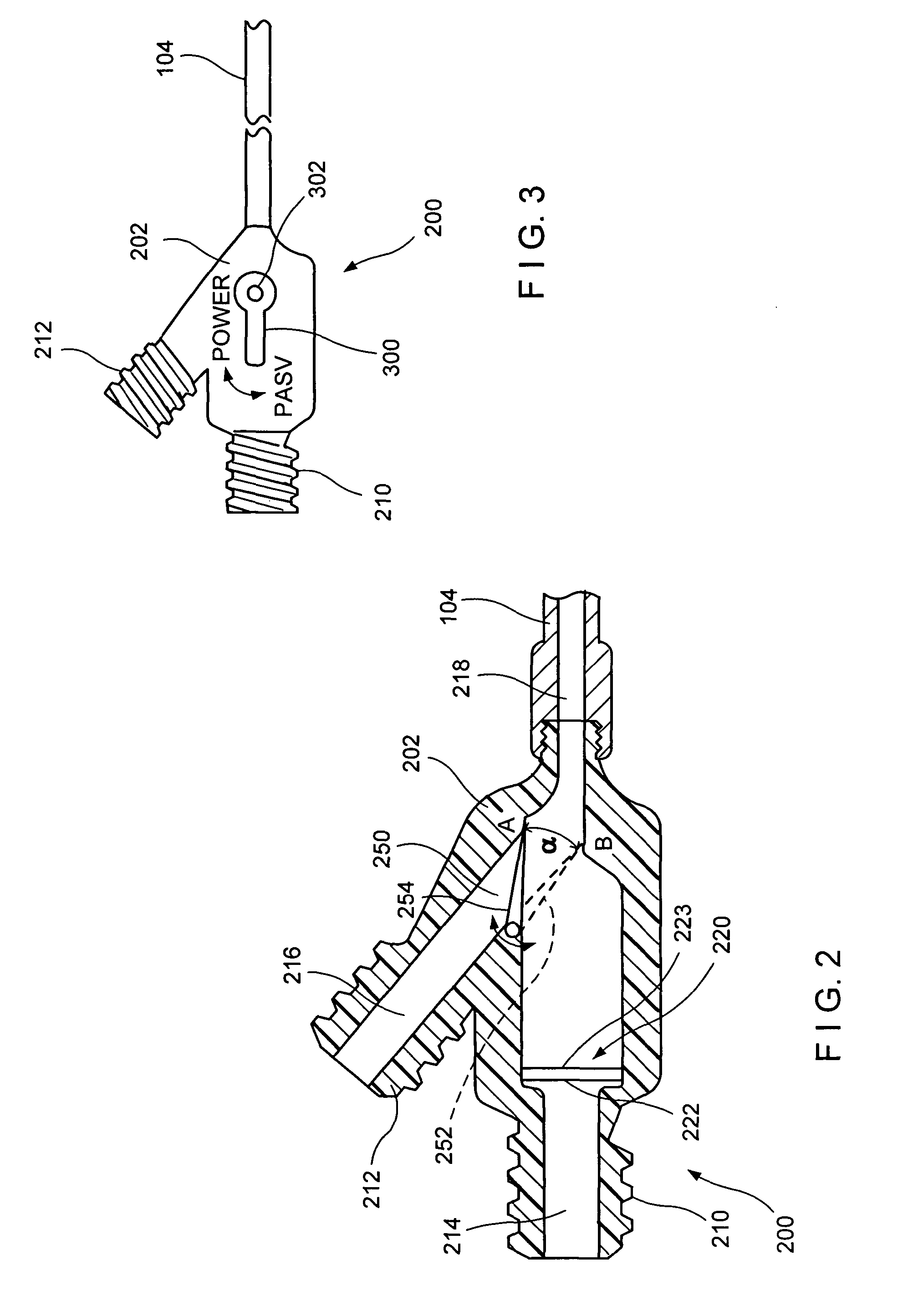
[0007]The present invention may be further understood with reference to the following description and the appended drawings, wherein like elements are referred to with the same reference numerals. The invention relates to devices for connecting a source of pressurized fluid to a valved catheter, without damaging the valve of the catheter. More specifically, the invention relates to a valve housing and connector for a semi-permanently implanted catheter bypassing the catheter's safety valve to avoid damage which might otherwise occur through the introduction of fluid at a high flow rate and / or pressure.

[0008]The proximal ends of semi-permanently implanted catheters generally extend out of the body and often include provisions for connection to external medical devices. For example, a semi-permanently implanted catheter may include a connector including a flow control valve which, as described above, seals the catheter when not in use and permits fluid flow therethrough when fluid tra...


PUM


Abstract

A valve assembly for a catheter comprising a housing having a lumen extending therethrough a first port opening to a proximal end of the lumen via a first port passage and a valve disposed in the first port passage, the valve being biased toward a closed configuration to prevent fluid flow therethrough when the first port passage is not in use in combination with a second port opening of the housing in fluid connection with a proximal end of the lumen via a second port passage.

Description

BACKGROUND OF THE INVENTION[0001]The treatment of chronic disease often requires repeated and prolonged access to the vascular system. As it is impractical and dangerous to insert and remove a catheter at every session, patients are often fitted with a semi-permanent catheter which is left in place for months or years.[0002]A valve may be used to seal the proximal end of such a semi-permanently implanted device when the device is not in use. One common type of valve is the Pressure Actuated Safety Valve (PASV), which open when a fluid pressure in the catheter exceeds a preselected threshold level. These PASV's often include a slitted membrane designed to remain closed when subject to pressures applied by the vascular system or through normal movement of the patient and to open when fluid pressure applied thereto to introduce fluids to or remove fluids from the vascular system.SUMMARY OF THE INVENTION[0003]In one aspect, the present invention is directed to a valve assembly for a cat...

Claims


Application Information

Patent Timeline
Patent Type & Authority Patents(United States)
IPC IPC(8): A61M5/00
CPCA61M25/0097A61M39/223A61M39/26A61M25/0075
Inventor MURPHY, NATHAN
Owner NAVILYST MEDICAL
Why Eureka
Try Eureka