Two-stage optimal power flow calculation method for power supply containing unified power flow controller

A technology of power flow controller and optimal power flow, applied in AC network circuits, wind power generation, electrical components, etc., can solve problems such as wind power instability

Inactive Publication Date: 2016-02-10
HOHAI UNIV
View PDF3 Cites 20 Cited by
  • Summary
  • Abstract
  • Description
  • Claims
  • Application Information

AI Technical Summary

Problems solved by technology

However, due to the characteristics of randomness, intermittency and instability of wind power, its

Method used


Image

  • Two-stage optimal power flow calculation method for power supply containing unified power flow controller
  • Two-stage optimal power flow calculation method for power supply containing unified power flow controller
  • Two-stage optimal power flow calculation method for power supply containing unified power flow controller

Examples


Embodiment Construction

[0051] The present invention will be further described below in conjunction with the accompanying drawings. The following examples are only used to illustrate the technical solution of the present invention more clearly, but not to limit the protection scope of the present invention.

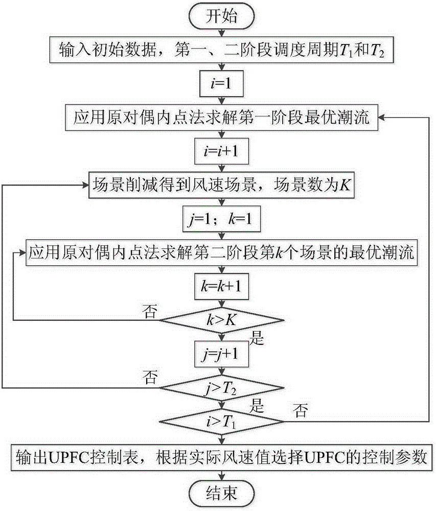
[0052] The present invention relates to a power system two-stage optimal power flow calculation method including a unified power flow controller, comprising the following steps:

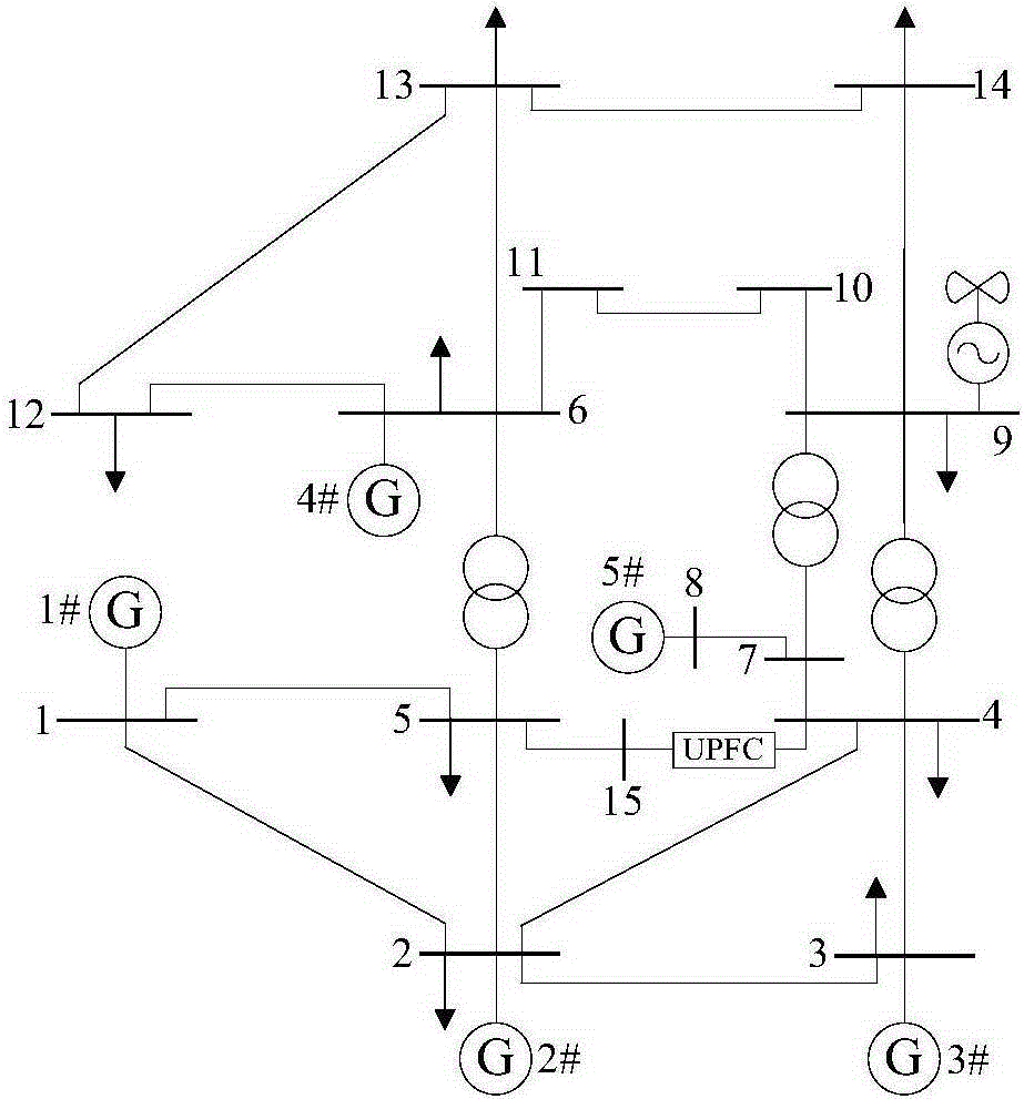
[0053] Step 1) Deduce the steady-state model of the unified power flow controller based on the power injection method: UPFC generally adopts a dual voltage source model, and its structure diagram is as follows Figure 4 As shown, mainly by the parallel controllable voltage source Impedance Z E and a series controllable voltage source Impedance Z B composition. Assuming that UPFC is installed at the s end of line sm, by adding a node r at the end of UPFC, UPFC becomes an independent branch to participate in syste...


PUM


Abstract

The invention discloses a two-stage optimal power flow calculation method for a power supply containing a unified power flow controller. A UPFC (unified power flow controller) model is deduced based on a power injection method; a two-stage scheduling model is proposed; optimal power flow calculation models containing the UPFC are established separately; the volatility of intermittent energy is corrected through regulating the control parameters of the UPFC, and the coordinative cooperation between the wind power and the UPFC is realized. The two-stage optimal power flow calculation method has the beneficial effects that (1) the model initially formulates a unit output plane in an intraday rolling scheduling stage to optimize the running cost; then a control policy table of the unified power flow controller is obtained in a real-time scheduling stage according to wind power output predication error, the running plan is modified in real time and a scheduling evidence is provided for the running scheduling staff; and (2) the volatility and the uncertainty of the wind power output can be coordinated by the rapid regulation of the control parameters of the unified power flow controller based on the flexible control capability of the unified power flow controller, and the economical performance and the safety of the system are improved.

Description

technical field [0001] The invention relates to a two-stage optimal power flow calculation method of a power system including a unified power flow controller, belonging to the technical field of power system operation analysis and control. Background technique [0002] Since the 21st century, the global energy crisis and environmental pollution have become increasingly prominent, and renewable clean energy such as wind power and solar energy has received more and more attention worldwide. However, due to the characteristics of randomness, intermittency and instability of wind power, its large-scale grid connection will bring great challenges to the stable operation of the power system. UPFC is an effective device to improve the stability of the power system. As a new type of flexible AC transmission device with the most comprehensive functions, the widest control range and the most superior characteristics so far, it can effectively improve the power flow distribution of the...

Claims


Application Information

Patent Timeline
IPC IPC(8): H02J3/00H02J3/46
CPCY02E10/76
Inventor 钱臻孙永辉卫志农孙国强臧海祥陈霜
Owner HOHAI UNIV
Why Eureka
Try Eureka