Combined wavefront and topography systems and methods

a topography and wavefront technology, applied in laser surgery, medical science, surgery, etc., can solve the problems of not adequately accounting for transverse ray movement from the measurement location, and traditional approaches that do not adequately account for transverse ray movement, so as to achieve the effect of convenient implementation

Active Publication Date: 2013-11-19
AMO DEVMENT
View PDF132 Cites 9 Cited by
  • Summary
  • Abstract
  • Description
  • Claims
  • Application Information

AI Technical Summary

Benefits of technology

[0005]Embodiments of the present invention provide systems and methods for generating a laser refractive treatment ablation target using wavefront and corneal topographical data. These techniques can involve finding the ablation target for laser vision correction using both wavefront eye refractor and corneal topography information, such that the ablation target provides the desired refractive state for the eye. It thus provides a customized solution for the eye that is to be treated and does so for the desired final result. Advantageously, these approaches can account for transverse ray movement from the measurement location to the point of refraction, for the obliquity of the refracting surface, and / or for local variations in the anterior corneal surface shape. Embodiments disclosed herein provide straightforward solutions for these effects that can be easily implemented.
[0006]In an exemplary approach, the wavefront exiting the uncorrected eye and the anterior corneal shape of the eye are measured. Both the exiting wavefront and the corneal shape can be used to determine the amount of tissue that must be removed at each corneal location to result in the desired refractive state for the eye. Full ray tracing can be used to account for oblique surface effects and transverse wavefront propagation effects so that the final surface will accurately create the desired refractive state. Thus the ablation target, if achieved by subsequent treatment, yields the desired refractive effect.

Problems solved by technology

Such approaches typically do not adequately account for transverse ray movement from the measurement location to the point of refraction, do not account for the obliquity of the refracting surface, and / or do not account for local variations in the anterior corneal surface shape.

Method used


Image

  • Combined wavefront and topography systems and methods
  • Combined wavefront and topography systems and methods
  • Combined wavefront and topography systems and methods

Examples


Embodiment Construction

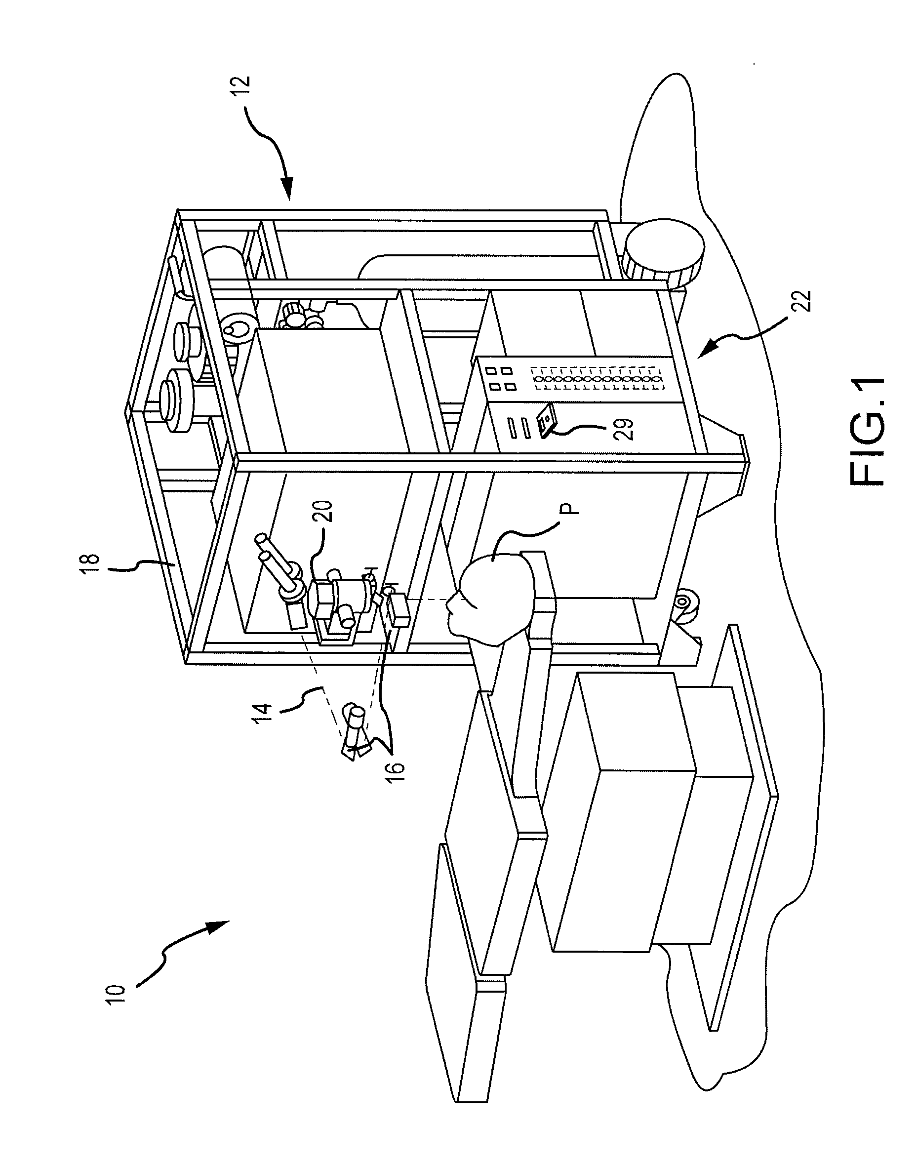
[0029]Embodiments of the present invention can be readily adapted for use with existing laser systems, wavefront measurement systems, and other optical measurement devices. Although systems, software, and method embodiments of the present invention are described primarily in the context of a laser eye surgery system, it should be understood the present invention may be adapted for use in alternative eye treatment procedures, systems, or modalities, such as spectacle lenses, intraocular lenses, accommodating IOLs, contact lenses, corneal ring implants, collagenous corneal tissue thermal remodeling, corneal inlays, corneal onlays, other corneal implants or grafts, and the like. Relatedly, systems, software, and methods according to embodiments of the present invention are well suited for customizing any of these treatment modalities to a specific patient. Thus, for example, embodiments encompass custom intraocular lenses, custom contact lenses, custom corneal implants, and the like, w...


PUM


Abstract

Methods, software, and systems are provided for determining an ablation target shape for a treatment for an eye of a patient. Techniques include determining wavefront information from the eye of the patient with a wavefront eye refractometer, determining anterior corneal shape information from the eye with a corneal topography device, and combining the wavefront information and the anterior corneal shape information to determine the ablation target shape.

Description

CROSS-REFERENCES TO RELATED APPLICATIONS[0001]This application is a nonprovisional of, and claims the benefit of priority to, U.S. Provisional Patent Application No. 60 / 917,579 filed May 11, 2007. This application is also related to U.S. patent application Ser. No. 11 / 769,054 filed Jun. 27, 2007. The complete disclosure of each of these filings is incorporated herein by reference for all purposes.BACKGROUND OF THE INVENTION[0002]Embodiments of the present invention are related to systems and methods for laser vision correction, and in particular to laser refractive correction using wavefront eye refractor and corneal topographical information.[0003]Often in the field of wavefront guided laser refraction, the ablation target is based on the uncorrected wavefront exiting the eye, as measured with a wavefront eye refractor, by converting the wavefront error to wavefront error in corneal tissue. Such approaches typically do not adequately account for transverse ray movement from the mea...

Claims


Application Information

Patent Timeline
Patent Type & Authority Patents(United States)
IPC IPC(8): A61B18/20
CPCA61F9/00806A61B3/1015A61B3/107A61B5/4836A61F9/00804A61F9/00814A61F9/00808A61F9/00812A61F2009/00848A61F2009/00872A61F2009/0088A61F2009/00882A61B5/0036
Inventor CAMPBELL, CHARLES E.
Owner AMO DEVMENT
Why Eureka
Try Eureka